Redundancy systems and methods in communications systems

a communication system and redundancy system technology, applied in the field of redundancy in communication systems, can solve the problems of unused capacity of redundant components, high cost of inclusion of completely inactive redundant components, and hot redundancy

Inactive Publication Date: 2006-01-03
WSOU INVESTMENTS LLC +1
View PDF5 Cites 59 Cited by
  • Summary
  • Abstract
  • Description
  • Claims
  • Application Information

AI Technical Summary

Benefits of technology

[0015]One broad aspect of the invention provides a redundancy method of managing requests in a control plane of a communication node, the communication node including a first control card and a second control card. The redundancy method involves defining one of the control cards to be in an active state and the other of the control cards to be in an inactive state, the control card in the inactive state having a reduced set of privileges compared to the control card in the active state; maintaining synchronicity of information stored on the control card in the active state and the control card in the inactive state such that the control card in the inactive state can assume responsibilities of the control card in the active state in case

Problems solved by technology

In communication systems, hot redundancy is frequently used in voice communication systems due to the high reliability requirements.
However, while hot redundancy ensures that the redundant component is always available in case of failure of the primary component, the inclusion of completely inactive redundant components is expensive.
The capacity of the redundant component is unused, other than to maintain synchronicity of system information with the primary component, until a failure occurs.
Also, such systems typically do have certain single point of failure scenari

Method used


Image

  • Redundancy systems and methods in communications systems
  • Redundancy systems and methods in communications systems
  • Redundancy systems and methods in communications systems

Examples


Embodiment Construction

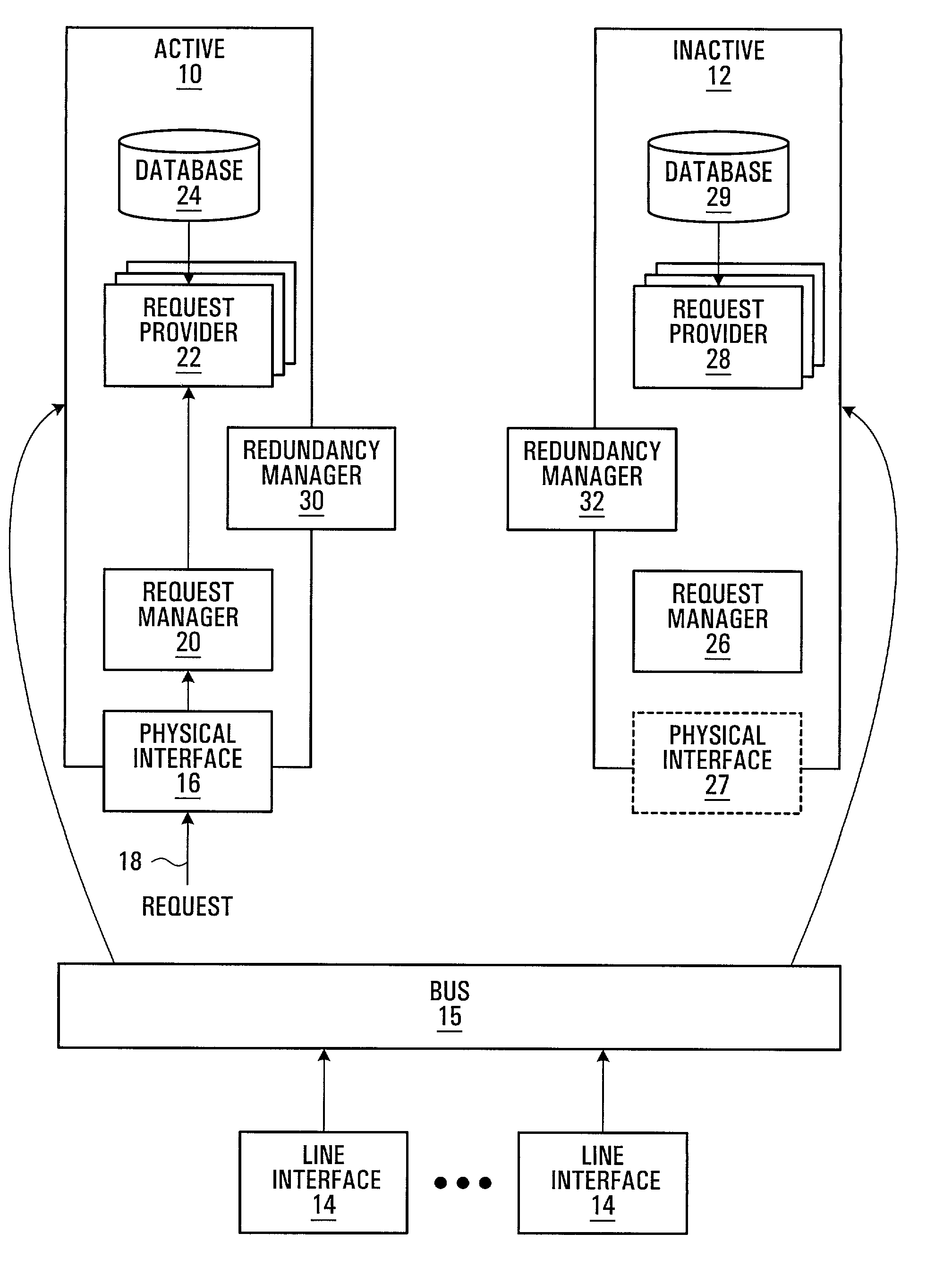
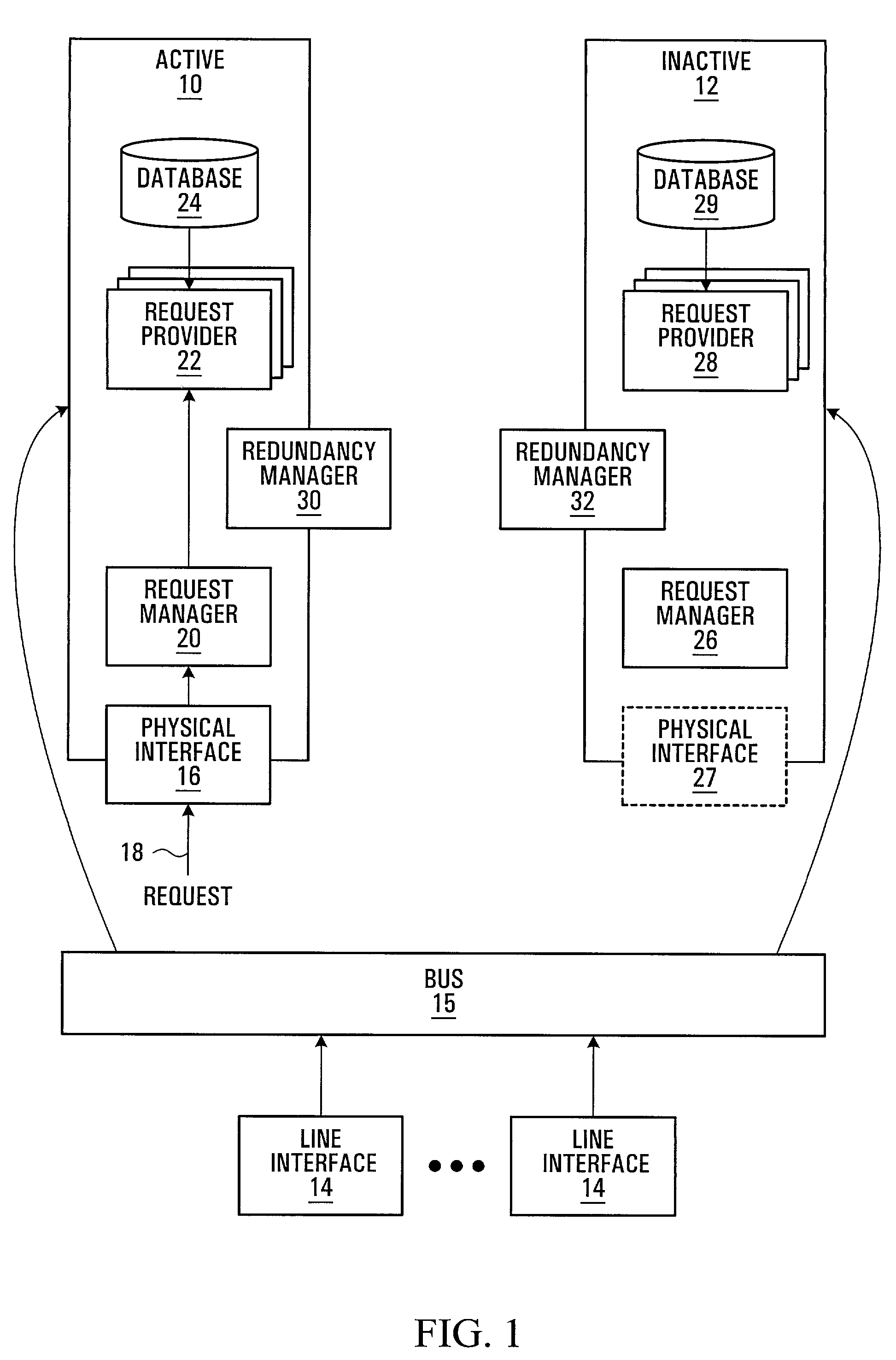
[0036]Referring to FIG. 1, a redundancy system according to one embodiment of the invention is shown. The redundancy system include two identical control cards 10,12. One control card 10 is shown in an active state, hereinafter referred to as the active (or primary) control card (ACC), and the other control card 12 is shown in an inactive state, hereinafter referred to as the inactive (or redundant) control card (ICC) 12. Each of the control cards 10 and 12 communicate with a plurality of line interface cards 14 via a bus 15. The control cards 10 and 12 and the line interface cards 14 are typically located within a shelf of a communications node, such as a metro optical node, within a communication system.

[0037]The ACC 10 includes a physical interface 16, such as an Ethernet port. The ACC 10 has a number of components typically connected to each other through a bus on the card with most components being individually addressable. Typically, an operating system is included which provi...


PUM


Abstract

A method and apparatus are provided for improving redundancy and load sharing in control cards in the control plane of a communication node. An active control card which receives a request passes the request to the inactive control card for processing if and only if the inactive control card is synchronized with the active control card and the inactive control card is able to process the request. Redundancy and load sharing are further improved if the active control card separates the processing of managing the request and the determination of a response to the request onto separate processors on the control card. In one embodiment, the control cards are OSPF modules in a router. Redundancy is effected by more accurately synchronizing the link state database of each OSPF module, and by allowing the state of each neighboring router to be determined only by the active OSPF module and not independently by any inactive OSPF module.

Description

RELATED APPLICATION[0001]This application claims the benefit of U.S. provisional application No. 60 / 289,545 filed May 9, 2001.FIELD OF THE INVENTION[0002]This invention relates to redundancy in communication systems.BACKGROUND OF THE INVENTION[0003]Redundancy is used in fault tolerant systems to deal with failures. When a primary component (either hardware or software) fails, a back-up component takes over the responsibilities of the primary component.[0004]An important place where redundancy may be used is the control plane of a communication system. The control plane is responsible for monitoring events in and the status of the network, and may be responsible for monitoring service level agreements. Typically a network node has a primary control card implementing the node's control plane responsibilities. A primary control card of the network node receives requests, and retrieves any system information necessary for responding to the requests. The system information may be stored ...

Claims


Application Information

Patent Timeline
IPC IPC(8): G06F17/30G06F11/20H04L12/56
CPCG06F11/1658G06F11/2005H04L45/00H04L45/28H04L45/586H04L45/60H04L45/22Y10S707/99953
Inventor JONES, DAVID JOSEPHPATRIARCHE, DOUGLAS HEATH
Owner WSOU INVESTMENTS LLC
Why Eureka
Try Eureka