
Disk recording and/or reproducing apparatus

a technology of recording and reproducing apparatus, applied in the field of recording and/or reproducing apparatus, can solve the problems of inability to read out and the signal recording surface looks considerably damaged

Inactive Publication Date: 2006-01-03
SONY CORP
View PDF7 Cites 12 Cited by
  • Summary
  • Abstract
  • Description
  • Claims
  • Application Information

AI Technical Summary

Benefits of technology

Effectively protects the signal recording surface from damage by preventing contact with foreign substances and ensuring reliable transportation and handling of disks of varying sizes without scratching or smudging, maintaining data integrity and disk condition.

Problems solved by technology

In consequence, when the signal recording surface is covered with the foreign substances or scratched, not only the signal recording surface looks considerably damaged but also a signal recorded beforehand cannot be read out from the optical disk and a new information signal cannot be written on the optical disk.

Method used


Image

  • Disk recording and/or reproducing apparatus
  • Disk recording and/or reproducing apparatus
  • Disk recording and/or reproducing apparatus

Examples


third embodiment

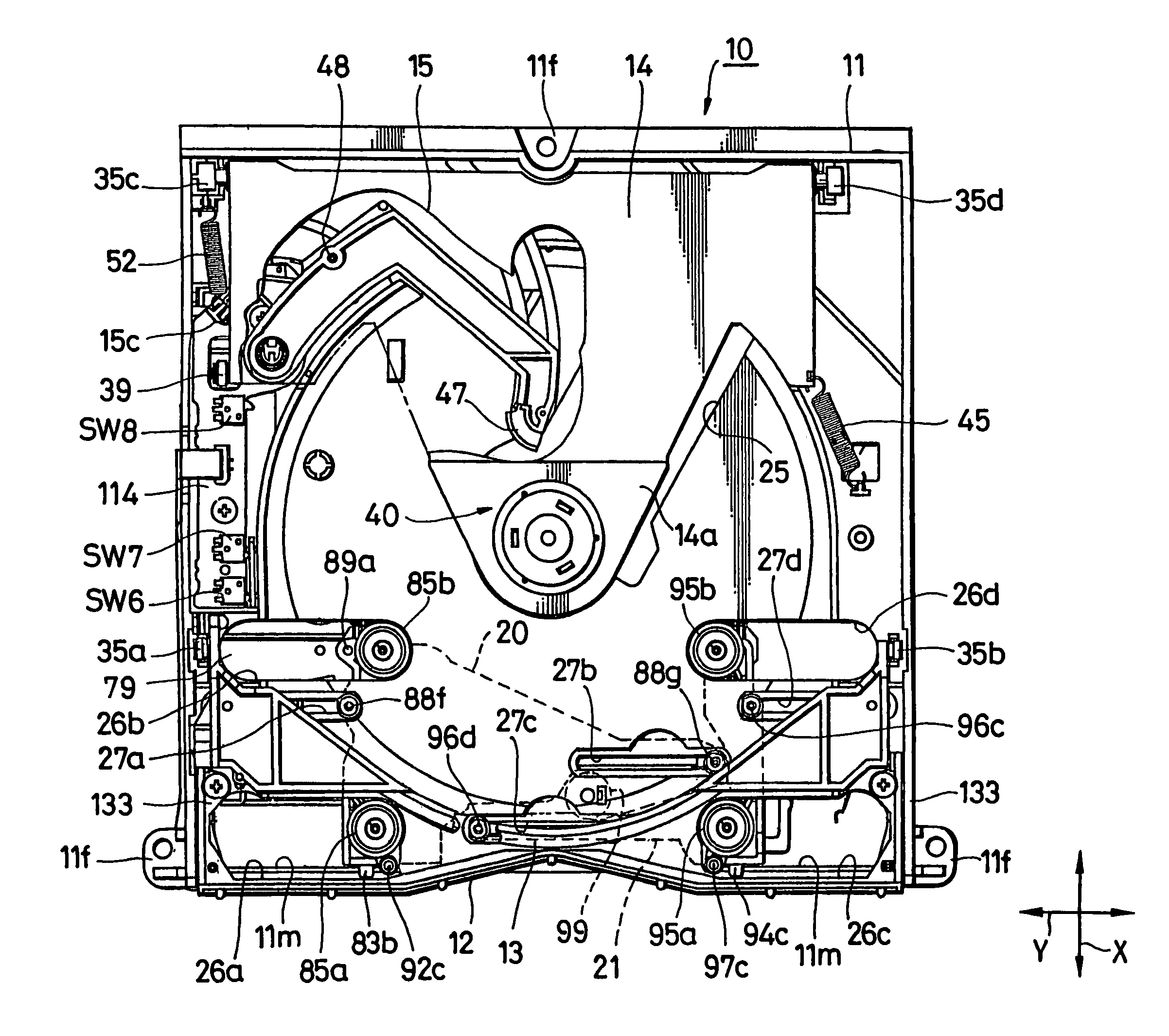
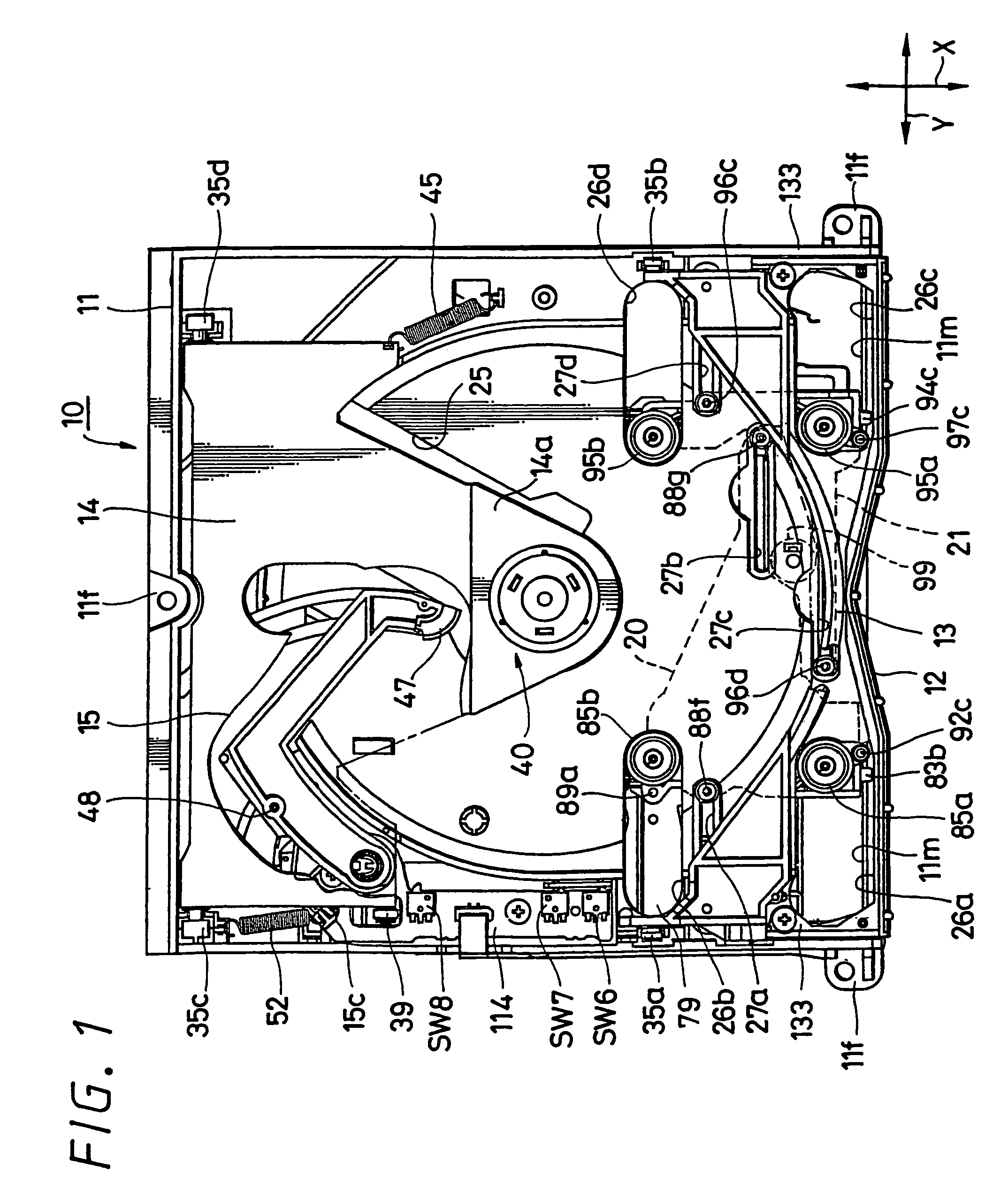
[0271]FIGS. 48A and 48B show the first transport member according to the present invention. A transport roller 140 serving as the first transport member according to this embodiment has a construction in which only a cushion member 141 which comes in contact with the outer peripheral edge of the optical disk D can rotate freely. Specifically, the transport roller 140 comprises a roller-like cushion member 141 and a holder 142 for rotatably holding this cushion member 141. The holder 142 includes a lower support portion 142a having a cone shape whose upper portion decreases in diameter and an upper support portion 142b having a cone shape whose lower portion decreases in diameter. A space S is set between the two support portions 142a and 142b. The cushion member 141 is rotatably provided in this space S between the two support portions.

[0272]Bearing members 143a, 143b are disposed at the upper and lower positions with respect to the cushion member 141. The cushion member 141 is fixe...

fourth embodiment

[0273]FIG. 49 shows the first transport member according to the present invention. A belt power transmission member 150 serving as the transport member shown in this embodiment is comprised of two running rollers 151, 152 and a running belt 153 stretched between the two running rollers 151, 152. The two running rollers 151, 152 are formed of rotating members of hand drum shape in which annular grooves 151a, 152a having arc-like concave portions continuing in the circumferential direction are formed on the outer peripheral surface. The running belt 153 is formed of a flat belt made of material such as rubber or engineering plastics, and this running belt is loaded on the annular grooves 151a, 152a of the two running rollers 151, 152.

first embodiment

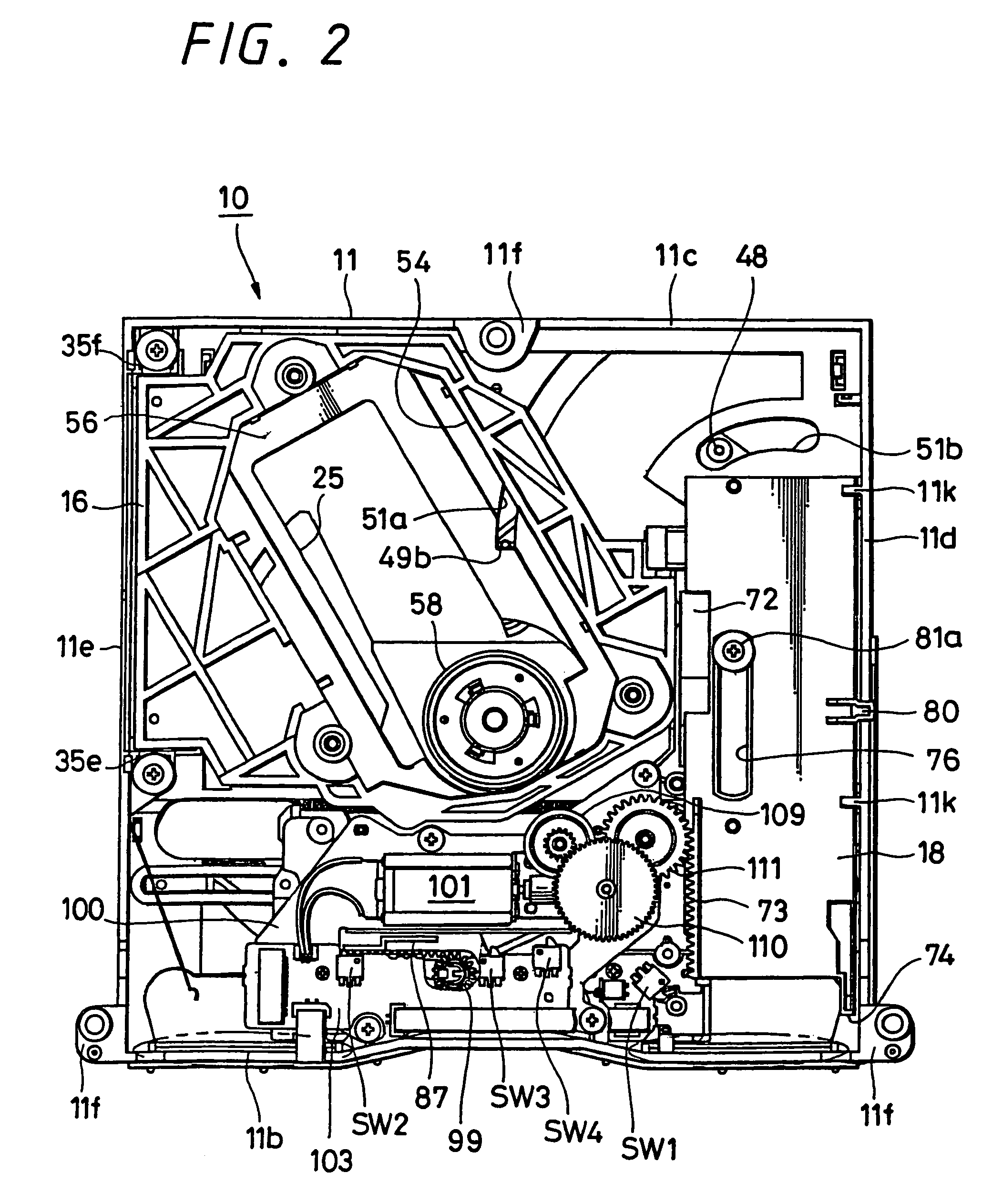
[0274]The belt power transmission member 150 having such a construction can be applied to the above-mentioned first embodiment as follows, for example. The first running roller 151 is rotatably supported by the first roller support shaft 88a of the drive-side guide lever 83, and the second running roller 152 is rotatably supported by the second roller shaft 88b of the drive-side guide lever 83. Then, any one of the running rollers (e.g. the first running roller 151) is provided with a gear portion and this gear portion is rotated by the drive motor 84.

[0275]Thus, the first running roller 151 can be rotated to drive and rotate the running belt 153, whereby the outer peripheral edge of the optical disk D is brought in contact with a conduit-like concave portion 153a formed on the outer peripheral surface of the running belt 153. As a result, similarly to the case of the above-mentioned drive rollers 85a, 85b, the optical disk D can be rotated and moved by rotation force given thereto....


PUM

PropertyMeasurementUnit
diameteraaaaaaaaaa
diameteraaaaaaaaaa
displacementaaaaaaaaaa

Abstract

The present invention relates to a disk recording and / or reproducing apparatus in which a disk-like recording medium such as an optical disk is transported between a disk loading portion provided for recording and / or reproducing information and a disk unloading portion for inserting and ejecting the disk-like recording medium.The disk recording and / or reproducing apparatus includes a pair of transport members for holding a disk-like recording medium in its diametrical direction, a drive means for driving a first transport member of the pair of transport members and giving rotation force to rotate and move the disk-like recording medium held between the pair of transport members and a space adjusting mechanism capable of adjusting a space by making the pair of transport members become close to or away from each other in response to the size of the disk-like recording medium.The disk-like recording medium can reliably be held in the diametrical direction by adjusting a space between the pair of transport members with the space adjusting mechanism in response to the size of the disk-like recording medium and the disk-like recording medium can be rotated, moved and transported by rotation force applied thereto. Therefore, when the disk is transported, the signal recording surface can be free from being touched, the signal recording surface can be prevented from being pressed by foreign material and the signal recording surface can be prevented from being scratched by the foreign material. Thus, an information signal can reliably be read and written.

Description

CROSS REFERENCE TO RELATED APPLICATIONS[0001]The present application is a Continuation Application of U.S. application Ser. No. 10 / 297,489, filed Jun. 4, 2003, which is a National Stage of PCT / JP02 / 03538, filed Apr. 9, 2002. In addition the present application claims the benefit of priority of Japanese Application No. 2001-110373, filed Apr. 9, 2001, the disclosure of which are all incorporated herein by reference.TECHNICAL FIELD[0002]The present invention relates to a disk recording and / or reproducing apparatus in which a disk-like recording medium such as an optical disk and a magneto-optical disk is transported between a disk loading portion which is provided to record and / or reproduce information and a disk entrance and exit slot through which the disk-like recording medium is inserted and ejected, and particularly to a disk recording and / or reproducing apparatus in which two or more than two disk-like recording mediums having different diameters can be reliably transported.BACK...

Claims


Application Information

Patent Timeline
Patent Type & Authority Patents(United States)
IPC IPC(8): G11B33/02G11B17/04G11B17/051
CPCG11B17/0288G11B33/02G11B17/0515G11B17/051G11B17/04
Inventor SUZUKI, YOSHIAKI
Owner SONY CORP
Learn More