
Movable door mounting assembly with trolley locking structure

a technology for mounting assemblies and moving doors, which is applied in the direction of transportation and packaging, manufacturing tools, wing accessories, etc., can solve the problems of difficult to remove tape, difficult to align difficulty in adjusting the studs with the moving trolley assembly, etc., and achieves the effect of simple locking structure and easy connection

Active Publication Date: 2006-01-10
LIBERTY HARDWARE MFG
View PDF11 Cites 54 Cited by
  • Summary
  • Abstract
  • Description
  • Claims
  • Application Information

AI Technical Summary

Benefits of technology

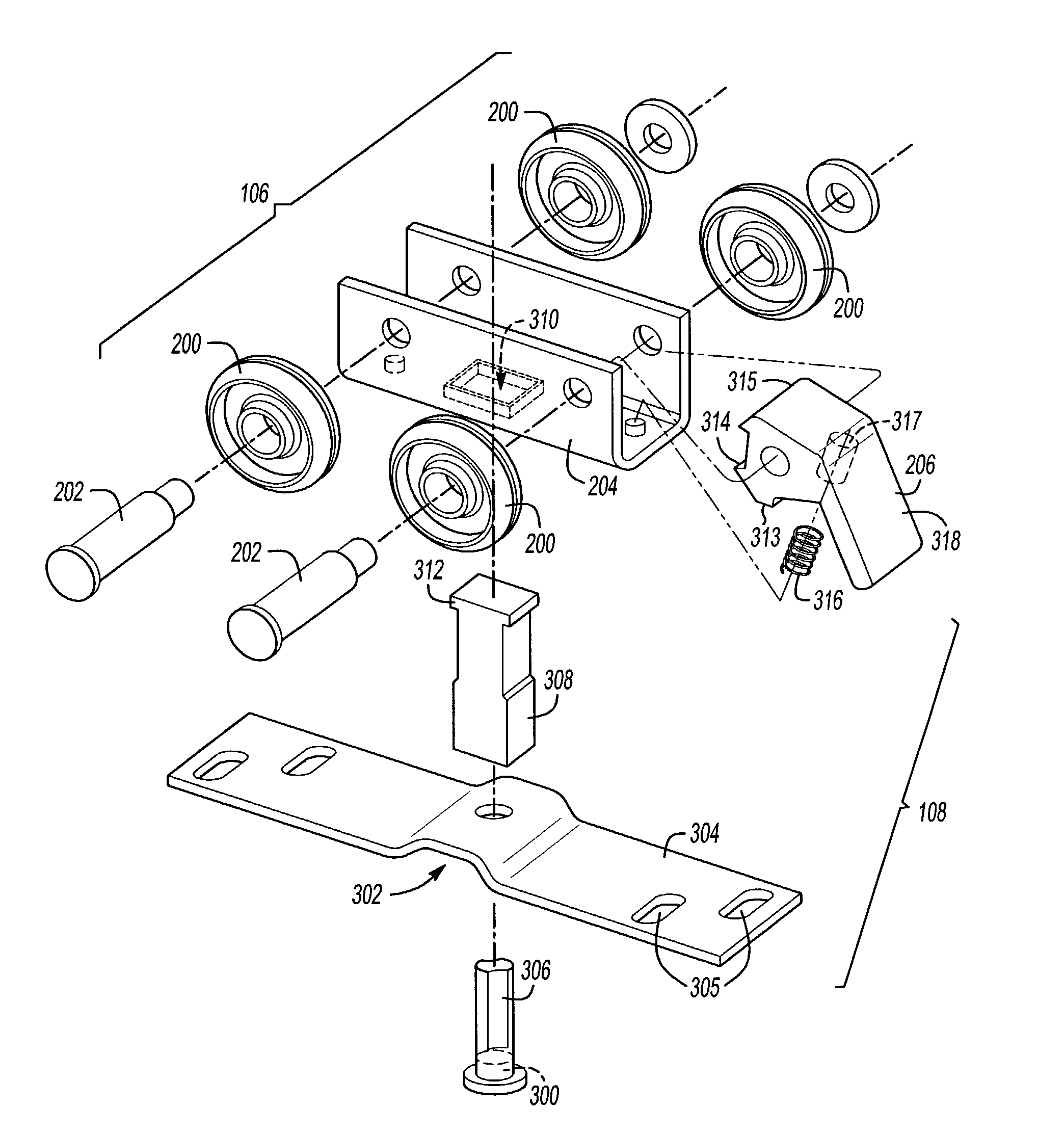
[0008]As a result, the invention provides a simple locking structure that makes it easier to connect the trolley assembly with the stud assembly to hang a movable door panel. Further, the automatic releasing feature of the locking structure eliminates the need to remove any components retaining the trolley assembly once the door panel has been hung.

Problems solved by technology

Because the trolley assembly has wheels that roll on the track, a user may have to chase the loose trolley with the stud while positioning the door in the door opening.
This problem is aggravated by the bulk of the door, which makes it difficult to align the stud with the moving trolley assembly.
Some users solve this problem by securing the trolley to the track with tape before inserting the stud, but removing the tape is difficult once the door is hung in the door opening.
As a result, any tape residue on the track or the trolley prevents the trolley from moving smoothly.

Method used


Image

  • Movable door mounting assembly with trolley locking structure
  • Movable door mounting assembly with trolley locking structure
  • Movable door mounting assembly with trolley locking structure

Examples


Embodiment Construction

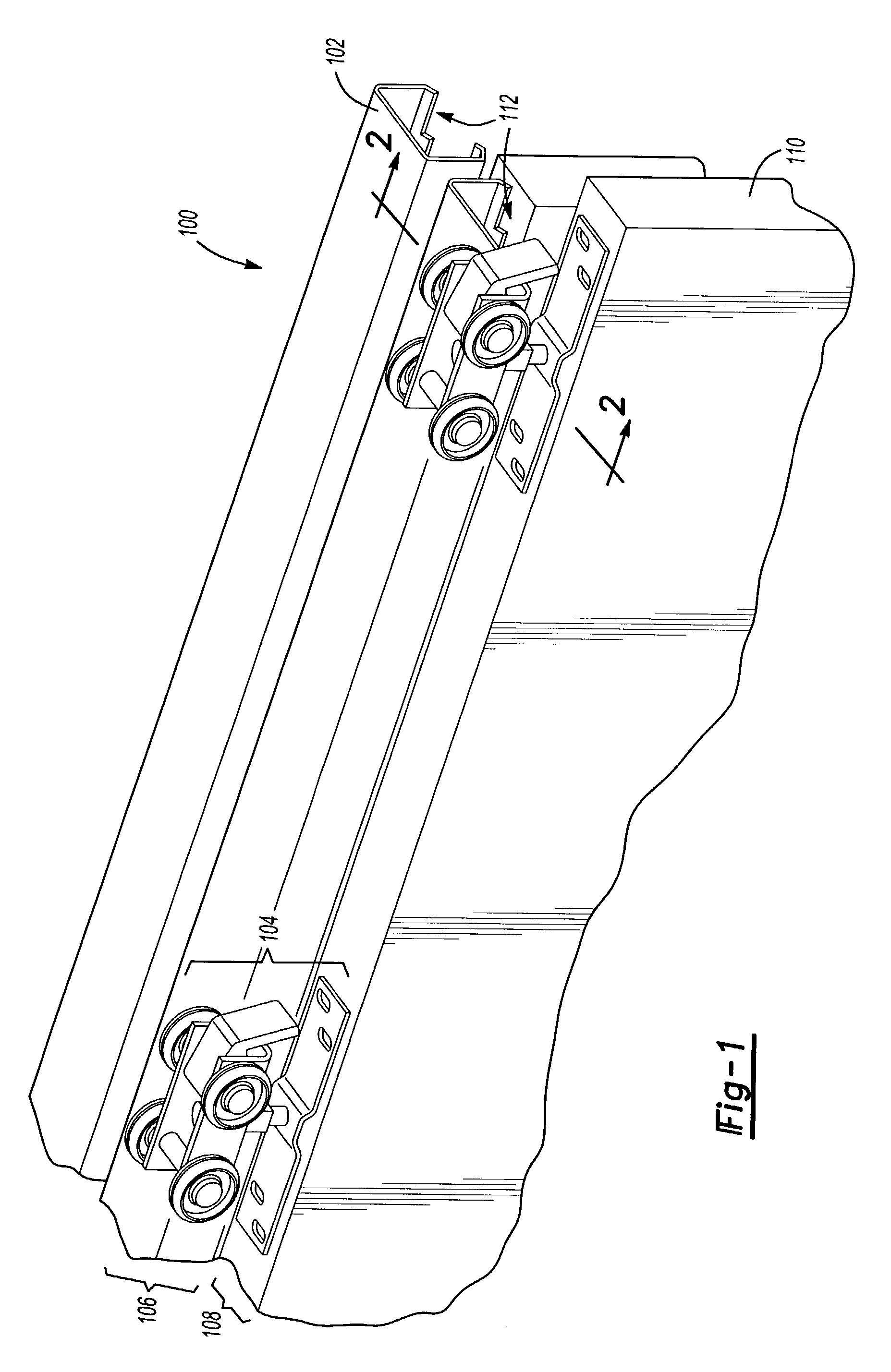
[0014]FIG. 1 is an example of a twin sliding door installation having a door mounting assembly 100 according to one embodiment of the invention. Note that the door mounting assembly 100 can also be applied to folding doors. In one embodiment, the door mounting assembly 100 includes a track 102 and a mounting structure 104. The mounting structure 104 includes a trolley assembly 106 and a stud assembly 108, allowing a door 110 to be mounted within a door opening. The track 102 is mounted in a doorway opening along a desired travel path for the mounting structure 104. The mounting structure 104 is movable within the track 102, allowing the door 110 to slide and / or pivot. In the embodiment shown in FIG. 1, two mounting structures 104 are inserted into the track 102 through a gap 112 at the end of the track 102.

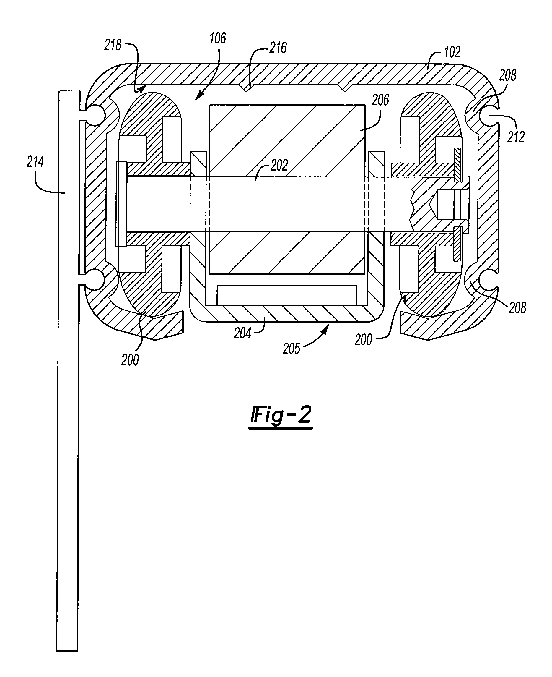
[0015]FIG. 2 is a section view of the track 102 and the trolley assembly 106 taken along line 2–2′ in FIG. 1. In the illustrated embodiment, four wheels 200 are mounted to two par...


PUM


Abstract

A movable door mounting assembly includes a stud assembly and a trolley assembly having a spring-biased cam piece that pivots between a normal position, which allows the trolley assembly to move freely on the track, and a locked position, which causes a locking surface on the cam piece to frictionally engage with a top surface of the track and hold the trolley assembly in place while the door is being hung. A catch in the stud assembly engages with the cam piece when the mounting assembly is fully assembled. Inserting the stud assembly into the trolley assembly, releases the cam piece from its locked position and, at the same time, positions the catch so that it engages with the cam piece when the door is hung.

Description

TECHNICAL FIELD[0001]The present invention relates to movable door installations and more particularly to mounting assemblies for movable door installations.BACKGROUND OF THE INVENTION[0002]Movable door mounting structure are used in both sliding door installations and folding door installations. Both installations allow the door to move along a horizontal track mounted at the top of a door opening, with the door being suspended from the track via the mounting assembly. Sliding door installations usually include two separate mounting structures, one at each end of the door, while folding door installations have a hinge connecting an outer door panel with a pivoting door panel and a movable mounting structure attached to the pivoting door panel.[0003]The mounting structure usually includes two cooperating assemblies: a trolley assembly inserted into the horizontal track and studs mounted to the top of the door. When the door is inserted into the door opening, the studs engage with th...

Claims


Application Information

Patent Timeline
Patent Type & Authority Patents(United States)
IPC IPC(8): E05D15/06E05D15/00
CPCE05D15/063E05Y2201/21E05Y2201/64E05Y2900/132Y10T16/364E05Y2600/60Y10T16/35Y10T16/381E05Y2600/528
Inventor DE OLIVEIRA, EGIDIO LUCAS
Owner LIBERTY HARDWARE MFG
Learn More