Eureka AIR delivers breakthrough ideas for toughest innovation challenges, trusted by R&D personnel around the world.

Method for partially exposing conductive strips of flat laminated cable

Inactive Publication Date: 2006-01-10
SCHLEUNIGER HLDG
View PDF12 Cites 6 Cited by
  • Summary
  • Abstract
  • Description
  • Claims
  • Application Information

AI Technical Summary

Benefits of technology

[0006]It is therefore the object of the invention to develop a process and an apparatus for producing windows in exactly predetermined parts above / below individual / all flat conductors of a multiconductor laminated cable, which windows are distinguished by clean and accurate contours and furthermore ensure good positional stability of the conductors. Finishing operations are to be substantially avoided.

Problems solved by technology

However, this considerably impairs the effectiveness of the known cost-saving production processes for flat cables.
Furthermore, the precision required in the positioning of the windows and the positional stability of the flat conductors during the use of this process, which stability still has to be maintained, cannot be guaranteed so that complicated finishing operations are often required.
Apart from the fact that here too complete and residue-free exposing of specific conductor segments cannot be reliably achieved, this process requires additional outlays for the extraction of the liberated plastic vapors which are harmful to health.
In addition, the remaining combustion residues may prevent a reliable electrical connection of the exposed segments to other conductors.
However, practical experience has shown that sufficiently accurate stripping which removes the insulation material without a residue, in particular in a dust-free manner, is not always achieved.

Method used


Image

  • Method for partially exposing conductive strips of flat laminated cable
  • Method for partially exposing conductive strips of flat laminated cable
  • Method for partially exposing conductive strips of flat laminated cable

Examples


Embodiment Construction

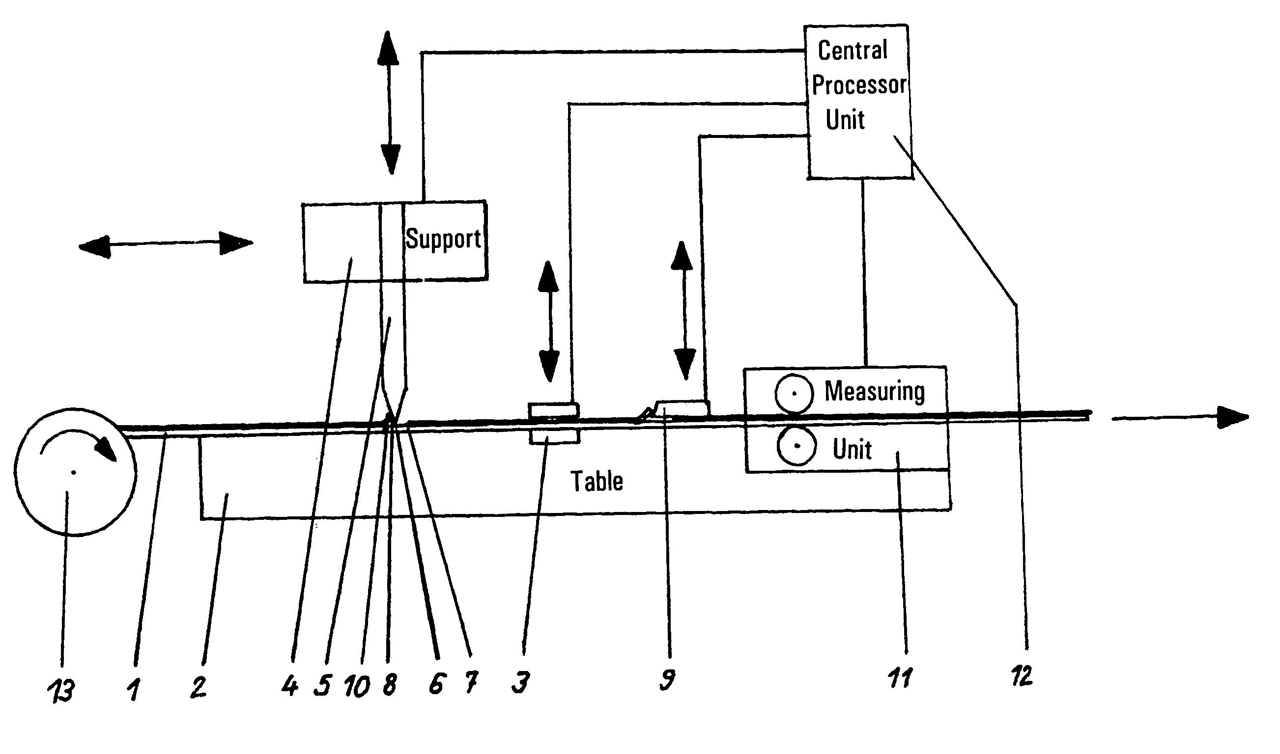
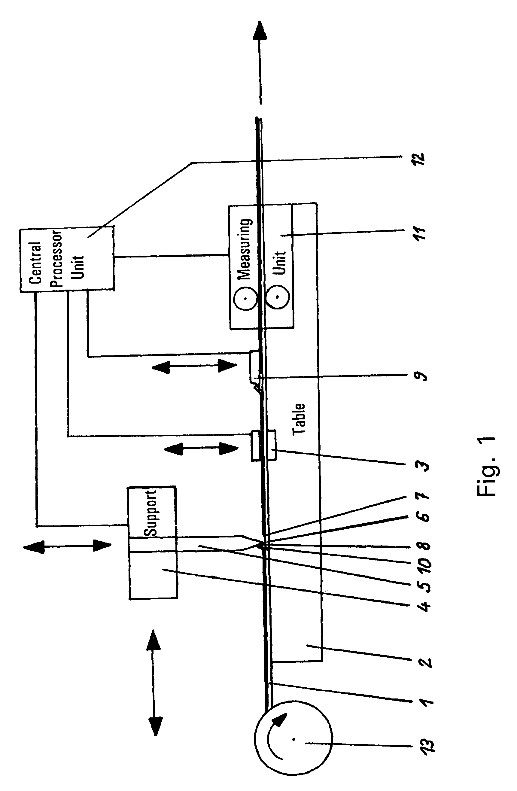
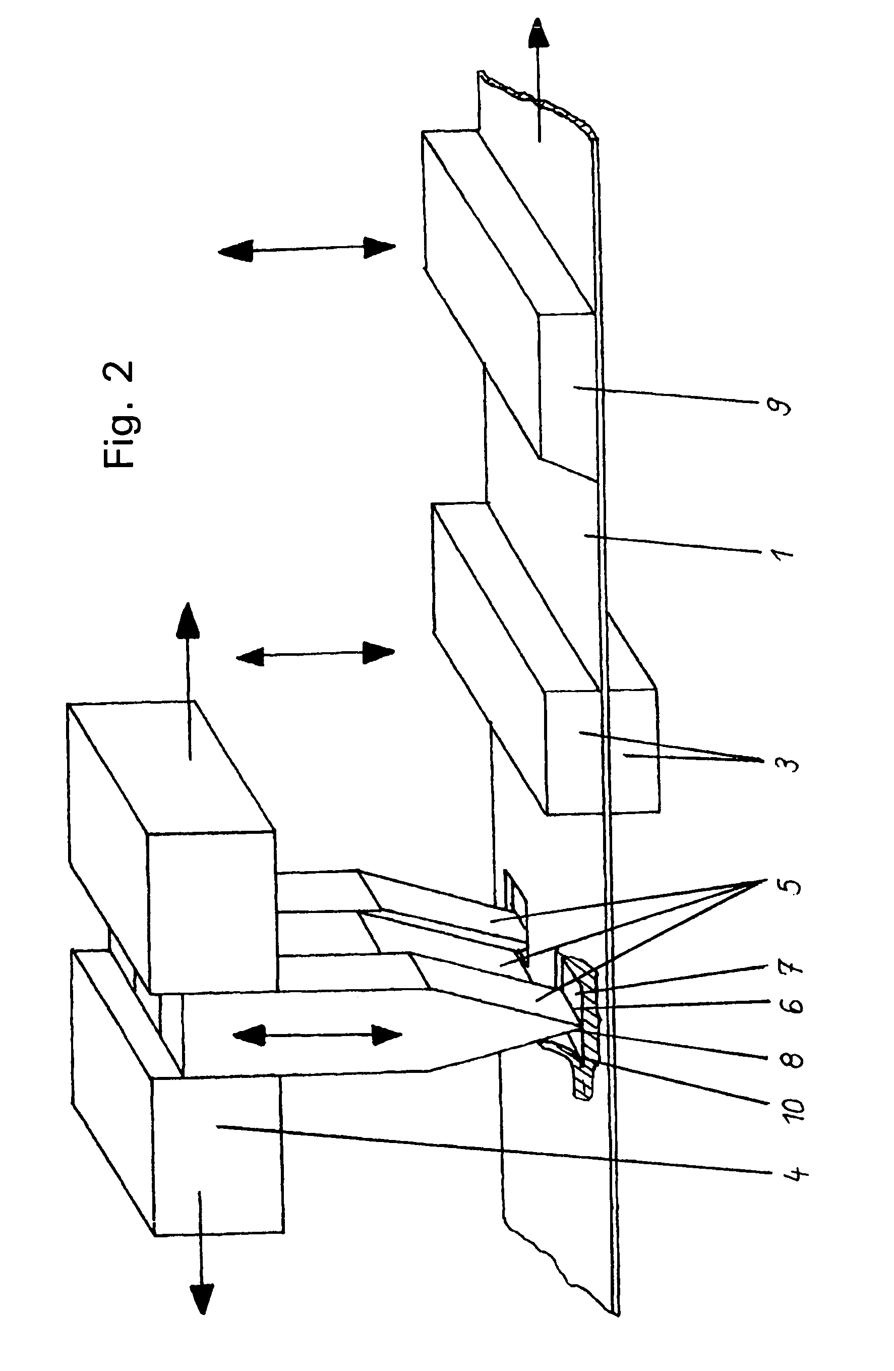
[0017]The laminated cable 1 is guided over the table 2 and aligned by means of the associated alignment and fixing unit 3 accurately in terms of position and distance with respect to the start of the cable and the tools. The wedge-shaped peeling tools 5 are arranged on the support 4 above the table 2, side by side and transverse to the flat cable 1. Their end faces tapering to a small angle each forming a sharp cutting edge 6 for cutting into the insulation layer and for subsequently peeling it off. Clean lateral cut edges of the windows 7 produced in the longitudinal direction of the flat cable 1 are achieved by additional sharp contours 8 at the triangular side faces of the peeling tools 5. All peeling tools 5 are longitudinally movable together with the support 4 and are arranged to be individually height-adjustable independently of one another in the support 4, so that they can be set up for cutting the windows 7 as defined beforehand in position and dimension into the insulatio...


PUM

PropertyMeasurementUnit
Lengthaaaaaaaaaa
Electrical conductoraaaaaaaaaa
Distanceaaaaaaaaaa

Abstract

The invention relates to a continuous process and an apparatus for partially exposing conductor tracks in fully insulated laminated cables according to specifiable parameters selectable in accordance with the subsequent conditions for use. The object of the invention is to insert windows in exactly predetermined parts above / below individual / all flat conductors of a multiconductor flat cable, which windows are distinguished by clean and accurate contours and furthermore ensure good positional stability of the conductors. The flat cable (1) is first fed to an apparatus and fixed on it in such a way that an individually feedable and individually movable peeling tool (5) can be coordinated in a defined manner with each flat conductor, both from above and from below, which peeling tool effects first an incision in the insulation layer, then peeling off down to the flat conductor and finally separation of the chip (10).

Description

FIELD OF THE INVENTION[0001]The invention relates to a continuous process and an apparatus for partially exposing the conductor strips of laminated cables completely insulated in the longitudinal direction, in accordance with specifiable parameters determined according to the subsequent conditions of use.[0002]In the production of flexible laminated cables by adhesively bonding an upper laminate web, cut to corresponding lengths of previously determined parts, it is customary to leave slots over the exposed conductors. However, this considerably impairs the effectiveness of the known cost-saving production processes for flat cables. Furthermore, the precision required in the positioning of the windows and the positional stability of the flat conductors during the use of this process, which stability still has to be maintained, cannot be guaranteed so that complicated finishing operations are often required.[0003]DE-GBM 89 08 274 discloses the adhesive bonding of an upper / lower lamin...

Claims


Application Information

Patent Timeline
IPC IPC(8): H01R43/00H01R43/28H02G1/12
CPCH02G1/1295H01R43/28Y10T29/514Y10T29/4919Y10T29/49192Y10T29/49117Y10T29/53274
Inventor ZEIBIG, DIETMARBUHLER, LEO
Owner SCHLEUNIGER HLDG
Why Eureka
Eureka Blog
Learn More