
Method for indicating the amount of ventilation inhomogeneity in the lung

a ventilation inhomogeneity and lung technology, applied in the direction of inhalators, sensors, medical devices, etc., can solve the problems of uneven ventilation of inspiration gas into the lungs, reducing the total blood oxygenation/cosub>2, and not gaining clinical acceptan

Inactive Publication Date: 2006-01-10
INSTRUMENTARIUM CORP
View PDF9 Cites 9 Cited by
  • Summary
  • Abstract
  • Description
  • Claims
  • Application Information

AI Technical Summary

Benefits of technology

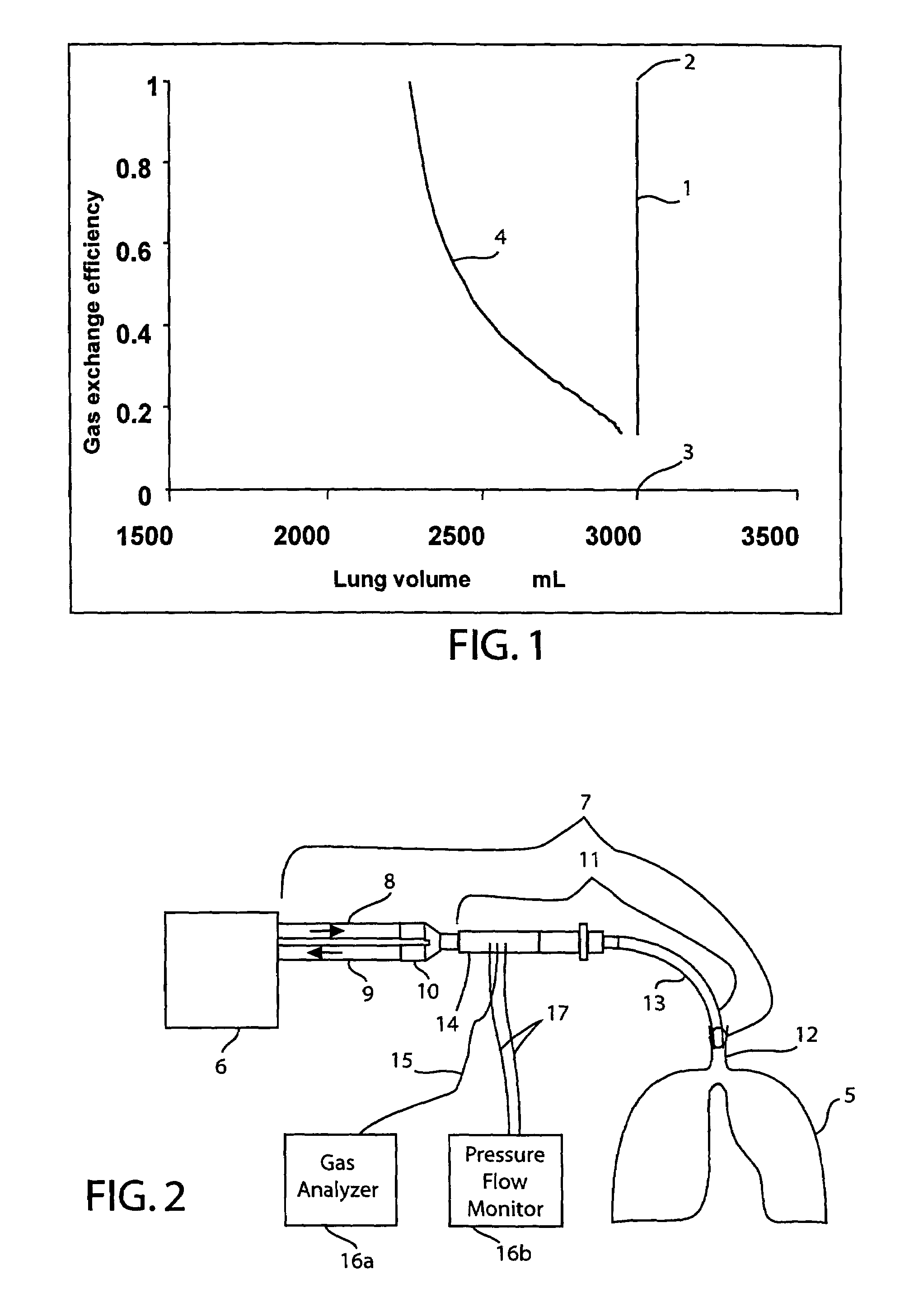
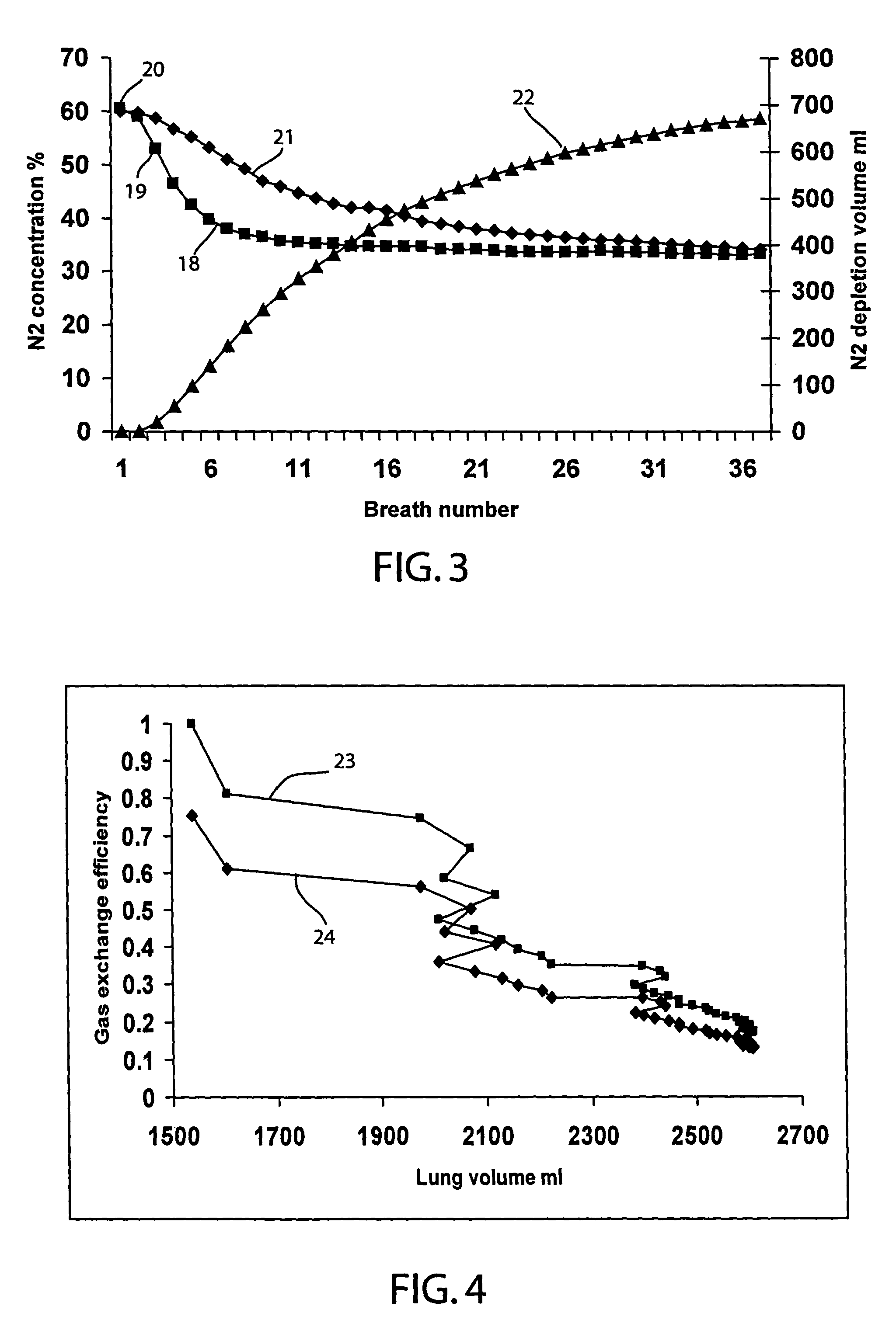
"The present invention provides a method for measuring lung volume and gas exchange efficiency by considering lung inhomogeneity. The method uses data series for inert gas concentration and single breath change in inert gas volume to calculate lung volume and gas exchange efficacy. The method has two advantages: it uses both data series, which are sensitive to different compartments of the lung, and the outcome is given in terms of lung volume and gas exchange efficacy, which are readily usable by the clinician. The method involves calculating lung volume from measured lung inert gas concentrations and volumetric changes, and matching it with the total gas exchange efficiency of the lung to obtain a global dilution factor. The method provides a clear representation of lung volumes where the gas exchange approaches zero."

Problems solved by technology

The lungs are always inhomogeneous with respect to these factors, and therefore the distribution of the inspiration gas flow into, or ventilation of, the lungs is uneven.
This reduces the total blood oxygenation / CO2 elimination carried out in the lungs.
Therefore, although these indices may have good correlation with ventilation inhomogeneity, they have not gained clinical acceptance.
Another problem with these methods is that in real multi-compartment lungs, the data series for the F and ΔVig values often represent different change response patterns, and when only one of these factors is considered, some part of the information will be lost.

Method used


Image

  • Method for indicating the amount of ventilation inhomogeneity in the lung
  • Method for indicating the amount of ventilation inhomogeneity in the lung
  • Method for indicating the amount of ventilation inhomogeneity in the lung

Examples


Embodiment Construction

[0023]In the preferred embodiment of the present invention described in detail below, a method for determining lung inhomogeneity is described. It should be understood that the drawings and specification are to be considered an exemplification of the principles of the invention, which is more particularly defined in the appended claims.

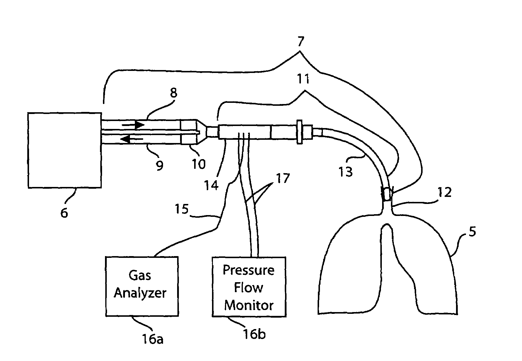
[0024]Referring to FIG. 2, a ventilation therapy apparatus is shown in which a patient's lungs 5 are connected to ventilator 6 via breathing circuit 7. The breathing circuit 7 comprises inspiration limb 8, expiration limb 9, Y-piece 10, and patient limb 11. During the inspiratory phase of a respiratory cycle, pressurized inspiration breathing gases of a desired composition are conducted from ventilator 6 through the inspiration limb 8, to Y-piece 10 and further through patient limb 11 to patient airways 12 and lungs 5. During inspiration, ventilator 6 closes the expiration limb 9 with an expiration valve (not shown) located within ventilator 6 to forc...


PUM


Abstract

A method of determining ventilation inhomogeneity in the lungs is provided. During the first step of the method, a lung volume series is calculated from a series of measured lung inert gas concentrations and lung inert gas volumetric change measured data series. As a second step, the series of lung volumes is completed with a series of value representing the total gas exchange efficiency in the lungs. A global inert gas dilution ratio may be used for this purpose. The gas exchange efficiency values are such that less ventilation is represented by lower numbers. As the third step, the gas exchange efficiency series is plotted as an ordinate and lung volume series as an abscissa to form a graph. From this graph both the lung volume and homogeneity of ventilation become directly apparent.

Description

BACKGROUND OF THE INVENTION[0001]The present invention is directed to a method for indicating ventilation efficacies occurring in the lungs of a subject and the volumetric portions of the lungs possessing differing ventilation efficacies. Such information is useful in determining the uniformity or homogeneity, or lack thereof, in the ventilation occurring in the subject's lungs. The method may also be used to determine the volume of the lungs.[0002]When breathing gases are inspired by a subject and pass from the patient airways into the lungs, the inspired breathing gases travel in the direction of the least flow impediment, of highest lung elasticity, and of smallest gas flow resistance. The lungs are always inhomogeneous with respect to these factors, and therefore the distribution of the inspiration gas flow into, or ventilation of, the lungs is uneven.[0003]When a given volume of inspired breathing gas VA flows into a lung compartment of volume V, the ventilation of that compart...

Claims


Application Information

Patent Timeline
Patent Type & Authority Patents(United States)
IPC IPC(8): A61M16/00A62B7/00F16K31/02A61B5/08A61B5/091A61M16/12
CPCA61B5/0813A61B5/091A61M16/0051A61M16/12A61M2230/43A61M2016/0036A61M2016/0042A61M2202/025A61M2016/0021A61M16/0833A61M16/085A61M16/021
Inventor HEINONEN, ERKKI
Owner INSTRUMENTARIUM CORP
Learn More