Process for the desulphurization of feed streams

a technology of desulphurization process and feed stream, which is applied in the direction of separation process, hydrogen sulfide, machine/engine, etc., can solve the problems of not being suitable for hot feed treatment, not being able to meet modern requirements, and not being able to achieve desulphurization at a sufficiently low level, so as to reduce the amount of sulphur present, reduce the effect of sulphur content and operation less efficien

Inactive Publication Date: 2005-06-14
JOHNSON MATTHEY DAVY TECH LTD
View PDF9 Cites 6 Cited by
  • Summary
  • Abstract
  • Description
  • Claims
  • Application Information

AI Technical Summary

Benefits of technology

[0010]It is therefore desirable to provide a process which enables the low levels of sulphur required in feeds to be achieved continuously, i.e. without interruption for absorbent replacement, and whilst minimising the costs incurred, by maximising the efficient use of the catalysts, and reducing the number of process vessels required.
[0022]The cooled stream is then passed to the lag catalyst bed. The temperature of the cooled stream is preferably in the region of 170° C. to 250° C. As this lower temperature is below the optimum operating temperature of the first sulphur-removing catalyst, it will operate less efficiently in the removal of sulphur from the feed in the lag catalyst bed. However, in this lag catalyst bed, the second sulphur-removing catalyst will be operating at optimum conditions and will serve to further reduce the amount of sulphur present in the feed.
[0023]Thus, it will be understood that some, preferably the majority, of the sulphur is removed by the relatively cost effective first sulphur-removing catalyst, e.g. the zinc oxide. The second sulphur-removing catalyst will then serve to remove additional sulphur such that the sulphur content is reduced to the required level. By this means, the amount of the relatively expensive second sulphur-removing catalyst required is minimised which has substantial cost-saving implications.
[0029]The first and second sulphur-removing catalysts may be provided in the lead and lag beds in any appropriate manner. In one arrangement they may be admixed. However, they may be in layers. The layers may be in contact or may be separate. Furthermore, the relative quantities of each absorbent may be easily varied in the light of the plant operating experience to provide the most effective operation for the sulphur content of the feed gas experienced.

Problems solved by technology

Whilst removal of the sulphur by this method has proved successful it suffers from the disadvantage that the level of desulphurisation achieved is not sufficiently low for modern requirements.
However, these catalysts suffer from the disadvantage that they are often expensive, and achieve a low sulphur loading.
A further drawback is that they are readily denatured at increased temperatures and therefore are not suitable for the treatment of hot feeds at the temperature at which zinc oxide is most effective.

Method used


Image

  • Process for the desulphurization of feed streams
  • Process for the desulphurization of feed streams

Examples


Embodiment Construction

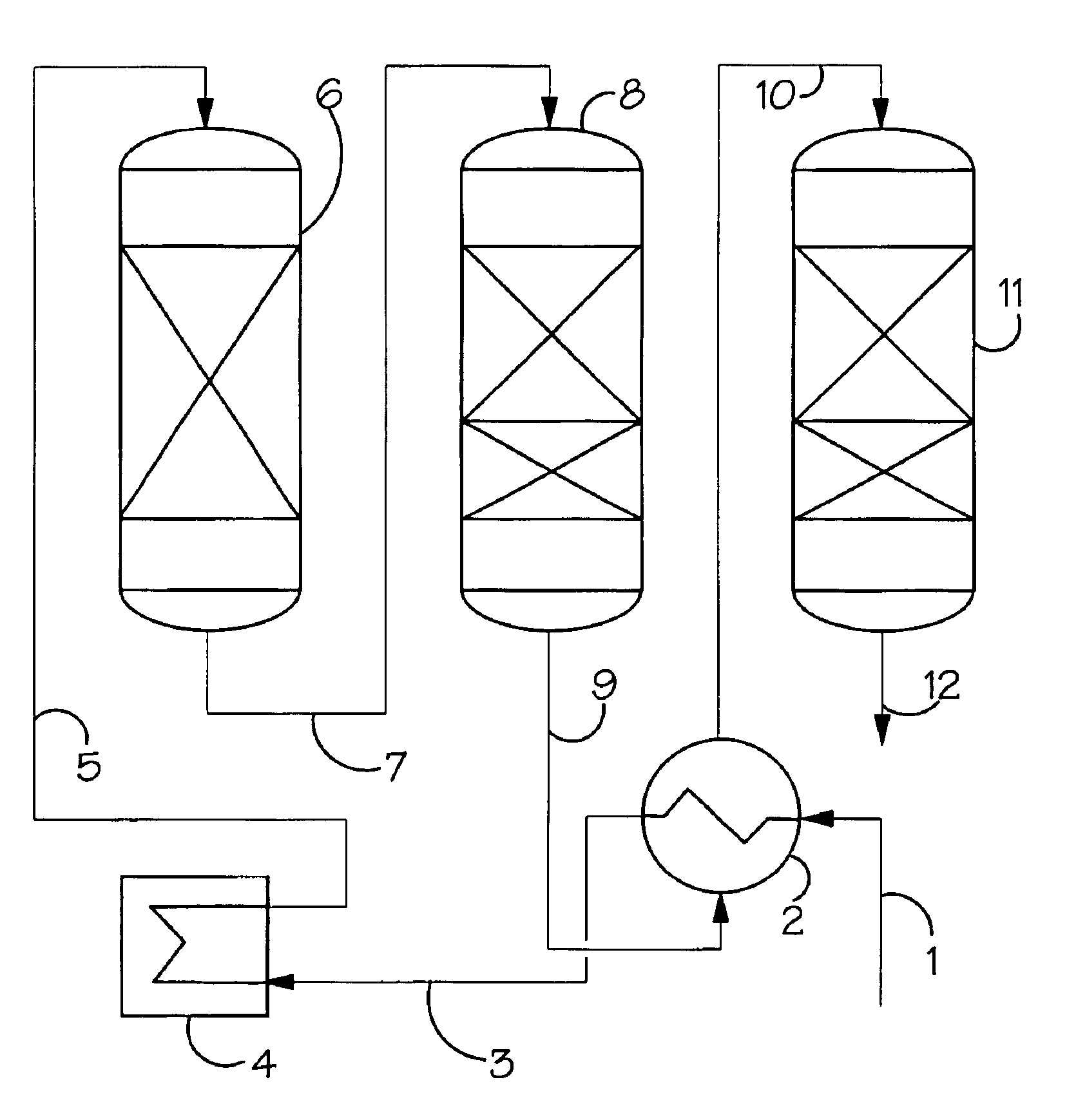
[0039]As illustrated in FIG. 1, a feedstock, such as a natural gas feedstock, is fed via line 1 to a gas / gas interchanger 2 where it is used to cool the hot partially sulphur depleted stream exiting the lead catalyst bed as described below.

[0040]The feed is then passed in line 3 to a desulphurisation interchanger 4 where the stream is heated. The heated stream is then passed in line 5 to an optional desulphurisation reactor 6.

[0041]The hot stream is then passed in line 7 to the lead catalyst bed 8 which will comprise an upper layer of zinc oxide and a lower layer of an ultra-purification catalyst. The bed will be operated at a temperature in the range of from about 260° C. to about 420° C. The zinc oxide will remove sulphur from the stream to an appreciable amount, typically down to 10 ppb at the start of its operation, but may be rising to 10 ppm at the end of its operating life.

[0042]The thus depleted stream, is then passed in line 9 to the interchanger 2 where it is cooled agains...


PUM

PropertyMeasurementUnit
temperatureaaaaaaaaaa

Abstract

The invention relates to: a process for the desulphurization of feed streams comprising: supplying a hot process stream to a lead catalyst bed (8) comprising a first sulphur-removing catalyst and a second sulphur-removing catalyst under conditions whereby sulphur is removed from the process stream by the first sulphur-removing catalyst and said second sulphur-removing catalyst does not effectively remove sulphur from the stream at the operating temperature of the lead catalyst bed for the duration of the bed's life; collecting a hot partially sulphur-depleted stream from the lead catalyst bed and cooling said stream; passing said cooled stream through a lag catalyst bed (11) comprising the first sulphur-removing catalyst and the second sulphur-removing catalyst under conditions whereby sulphur is removed from the process stream by the second sulphur-removing catalyst and said first sulphur-removing catalyst removes sulphur less efficiently from the stream at the operating temperature of the lag catalyst bed; and recovering said sulphur-depleted stream from the second catalyst bed. In addition it relates to, apparatus for the desulphurization of feed streams which comprises: a lead catalyst bed (8) comprising a first sulphur-removing catalyst and a second sulphur-removing catalyst capable of operating under conditions whereby sulphur is removed from the process stream by the first sulphur-removing catalyst and said second sulphur-removing catalyst does not effectively remove sulphur from the stream at the operating temperature of the lead catalyst bed (8) throughout the lead bed's operating life; means (9) for collecting a hot partially sulphur-depleted stream from the lead catalyst bed (8) and cooling said stream; a lag catalyst bed (11) comprising the first sulphur-removing catalyst and the second sulphur-removing catalyst capable of operating under conditions whereby sulphur is removed from the process stream by the second sulphur-removing catalyst and said first sulphur-removing catalyst does not efficiently remove sulphur from the stream at the operating temperature of the lag catalyst bed(11).

Description

BACKGROUND OF THE INVENTION[0001]The present invention relates to a desulphurisation process. More particularly, the present invention relates to the removal of sulphur compounds such as hydrogen sulphide from process streams. Most particularly, the present invention relates to the removal of sulphur compounds from hydrocarbon streams.[0002]Hydrocarbon process streams often comprise a significant quantity of sulphur compounds. For example, a gaseous hydrocarbon feed may comprise in excess of 50 ppm by volume expressed as equivalents of hydrogen sulphide.[0003]It is generally desirable to remove these sulphur compounds from the feed or at least to reduce them to a low level, for example to a level in an amount of about less than 5 ppm by volume. Indeed, more recently, there has been a demand for the sulphur content to be reduced to much lower levels, for example of the order of 1 ppm by volume or less.[0004]One method of sulphur removal that has been used is to contact the feed with ...

Claims


Application Information

Patent Timeline
Patent Type & Authority Patents(United States)
IPC IPC(8): C10G25/00
CPCC10G25/00
Inventor BENCE, ROGERLITTLEWOOD, STEPHEN CAIGEASTLAND, PHILIP HENRY DONALD
Owner JOHNSON MATTHEY DAVY TECH LTD
Why Eureka
Try Eureka