Accelerator pedal device

a technology of accelerator pedal and accelerator pedal, which is applied in the direction of driver interaction, driver input parameters, electric energy management, etc., can solve the problems of difficult to immediately recognize whether the accelerator pedal is in an acceleration zone or a deceleration zone, and the acceleration tends to be decelerated in a manner, so as to achieve easy recognition

Active Publication Date: 2014-04-22
HONDA MOTOR CO LTD
View PDF15 Cites 3 Cited by
  • Summary
  • Abstract
  • Description
  • Claims
  • Application Information

AI Technical Summary

Benefits of technology

[0006]The present invention has been made in view of the above problems. It is an object of the present invention to provide a control apparatus which is capable of preventing a vehicle from being decelerated in a manner not intended by the driver of the vehicle.
[0007]Another object of the present invention is to provide a control apparatus which allows the driver of a vehicle to easily recognize switching between the generation of a driving force and the generation of a braking force on the vehicle.
[0010]The reaction force controller may increase the reaction force when the operation quantity changes across the first threshold value or the second threshold value. The reactive force is increased when the vehicle switches from a state wherein the driving force or the braking force is generated to a state wherein the vehicle can travel by inertia, or when the vehicle switches from the state wherein the vehicle can travel by inertia to the state wherein the driving force or the braking force is generated. Therefore, the driver is capable of easily recognizing the operation quantity for such state changes.
[0012]The reaction force controller may set the reaction value at the time the operation quantity is greater than the second threshold value to be greater than the reaction value at the time the operation quantity lies between the first threshold value and the second threshold value. The reaction force is thus smaller when the vehicle is allowed to travel by inertia than when the driving force is generated. The driver can thus positively utilize traveling by inertia. When the driving force is generated, the reaction force may be increased in view of the presence of a vehicle ahead, a curve, a traffic signal, a stop sign, etc., letting the driver know a need for deceleration.
[0014]The accelerator pedal device may further include an operating speed detector for detecting an operating speed of the accelerator pedal, wherein the travel controller may increase the first threshold value or reduce the second threshold value if the operating speed exceeds a threshold value therefor for judging a degree of acceleration or deceleration of the vehicle. If the operating speed of the accelerator pedal is greater than the threshold value for the operating speed, therefore, the range of operation quantities which allows traveling by inertia thus becomes gradually reduced. If there is a reduced need for traveling by inertia, then the operating speed for the vehicle to change from acceleration or cruising to quick deceleration or from deceleration or cruising to quick acceleration may be set as the threshold value for the operating speed to shorten the time to start traveling by inertia for thereby quickly achieving quick acceleration or quick deceleration.

Problems solved by technology

However, when an engine brake is applied, the vehicle tends to be decelerated in a manner not intended by the driver.
Consequently, the driver finds it difficult to immediately recognize whether the accelerator pedal is in an acceleration zone or a deceleration zone.

Method used


Image

  • Accelerator pedal device
  • Accelerator pedal device
  • Accelerator pedal device

Examples


embodiment

A. Embodiment

[0024]A vehicle incorporating an accelerator pedal device according to an embodiment of the present invention will be described below with reference to the drawings.

1. Configuration of Vehicle 10

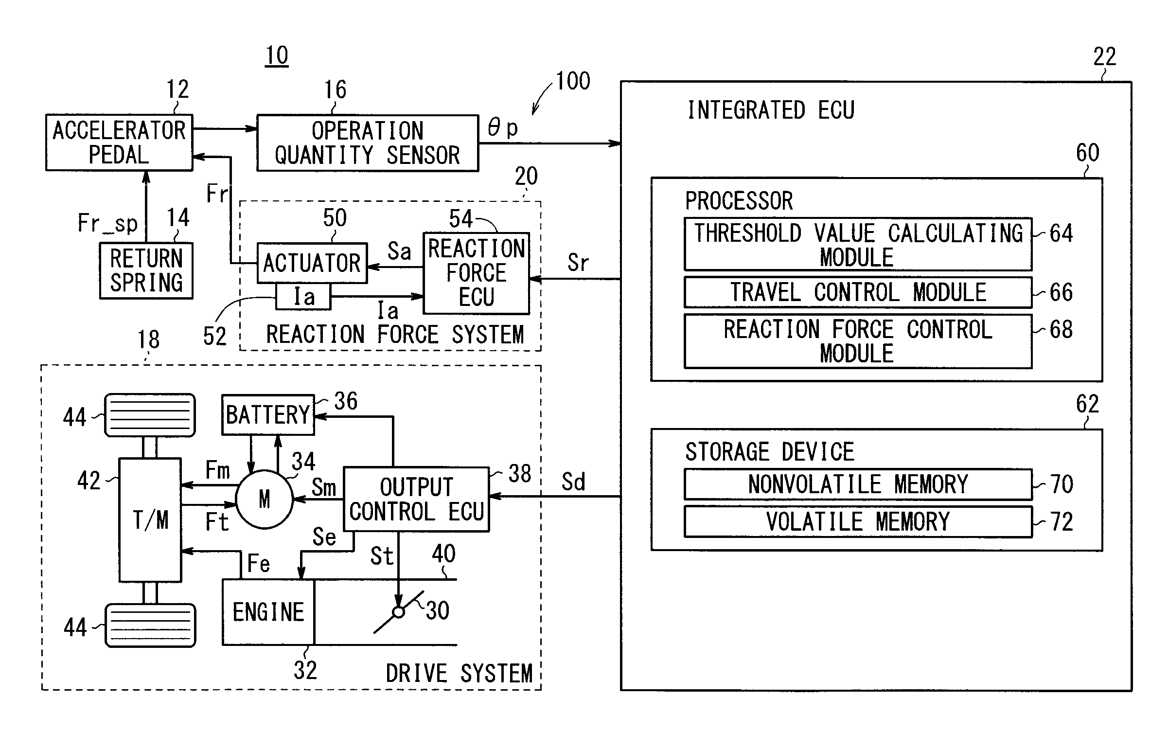
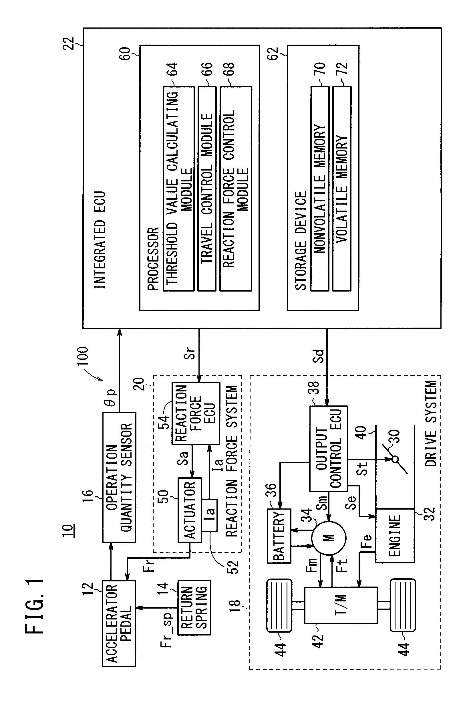
[0025]FIG. 1 is a block diagram of a vehicle 10 incorporating an accelerator pedal device 100 according to an embodiment of the present invention. The vehicle 10 comprises a hybrid vehicle, for example. Alternatively, the vehicle 10 may be an electric vehicle including a fuel cell vehicle. The vehicle 10 includes an accelerator pedal 12, a return spring 14 for applying a reaction force Fr_sp [N] to the accelerator pedal 12, an operation quantity sensor 16 (operation quantity detector), a drive system 18, a reaction force system 20, and an integrated electronic control unit (hereinafter referred to as “integrated ECU 22”).

[0026]The operation quantity sensor 16 detects a quantity by which the accelerator pedal 12 is depressed from its original position (operation quantity θp) [deg...


PUM


Abstract

An accelerator pedal device provided with a driving control device. The driving control device generates a braking force for braking a vehicle when the operation quantity of an acceleration pedal is below a first threshold value, and generates a driving force for driving the vehicle when the operation quantity exceeds a second threshold value larger than the first threshold value. The driving control device does not generate either the driving force or the braking force, and allows the vehicle to drive inertially, when the operation quantity ranges from the first threshold value to the second threshold value.

Description

TECHNICAL FIELD[0001]The present invention relates to an accelerator pedal device for controlling the generation of a driving force and a braking force on a vehicle depending on the operation quantity of an accelerator pedal.BACKGROUND ART[0002]There has been an accelerator pedal device for controlling the acceleration and deceleration of a vehicle based on the operation of an accelerator pedal {Japanese Laid-Open Patent Publication No. 2001-260713 (hereinafter referred to as “JP2001-260713A”)}. According to JP2001-260713A, when the operation quantity of an accelerator pedal (1) is equal to or smaller than a prescribed value (T1), a throttle opening degree (E) is set to zero and the braking quantity (B) of a brake disk (14) is adjusted (see, for example, the abstract, FIGS. 2, 3, and 7 of JP2001-260713A).[0003]There is also known an arrangement for imparting a reaction force from an actuator to an accelerator pedal depending on the operation quantity of the accelerator pedal {Intern...

Claims


Application Information

Patent Timeline
Patent Type & Authority Patents(United States)
IPC IPC(8): G06F7/70
CPCB60W10/08F02D29/02B60W10/06B60W30/18127Y02T10/6286F02D11/10B60W30/1882B60W2540/10B60W20/00F02D2200/602B60W30/18072F02D11/02B60W2540/106B60W30/18181B60W2540/103B60W50/16B60W2030/1809F02D11/105B60L15/2009B60L7/18B60L7/14B60L2260/24B60L7/26B60L2260/44Y10T74/20534B60L11/14B60L2240/423B60L2260/30Y02T10/7077B60L11/18B60L11/1887B60L7/12B60L2250/26Y02T10/642B60L2250/28B60L11/1803Y02T90/34B60L2240/12Y02T10/70Y02T10/7275B60L2260/26B60L50/16B60L50/51B60L58/40Y02T10/62Y02T10/64Y02T10/7072Y02T10/72B60W30/14Y02T90/40
Inventor TAKIGUCHI, HIROTAKASUGIMOTO, YOICHITAKEMASA, KOICHIROTSURUTANI, TAISUKE
Owner HONDA MOTOR CO LTD
Why Eureka
Try Eureka