Fluid control apparatus
- Summary
- Abstract
- Description
- Claims
- Application Information
AI Technical Summary
Benefits of technology
Problems solved by technology
Method used
Image
Examples
first embodiment
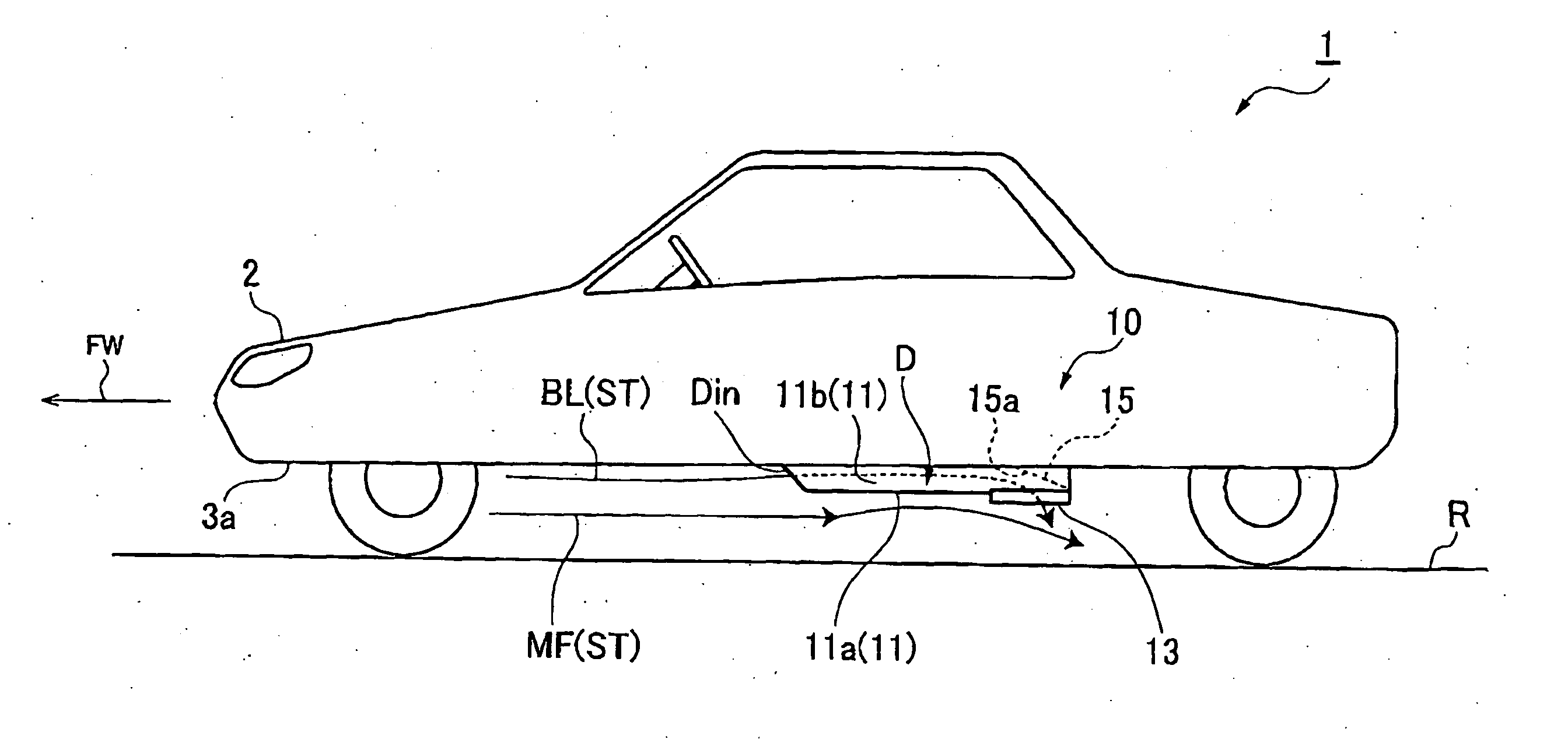
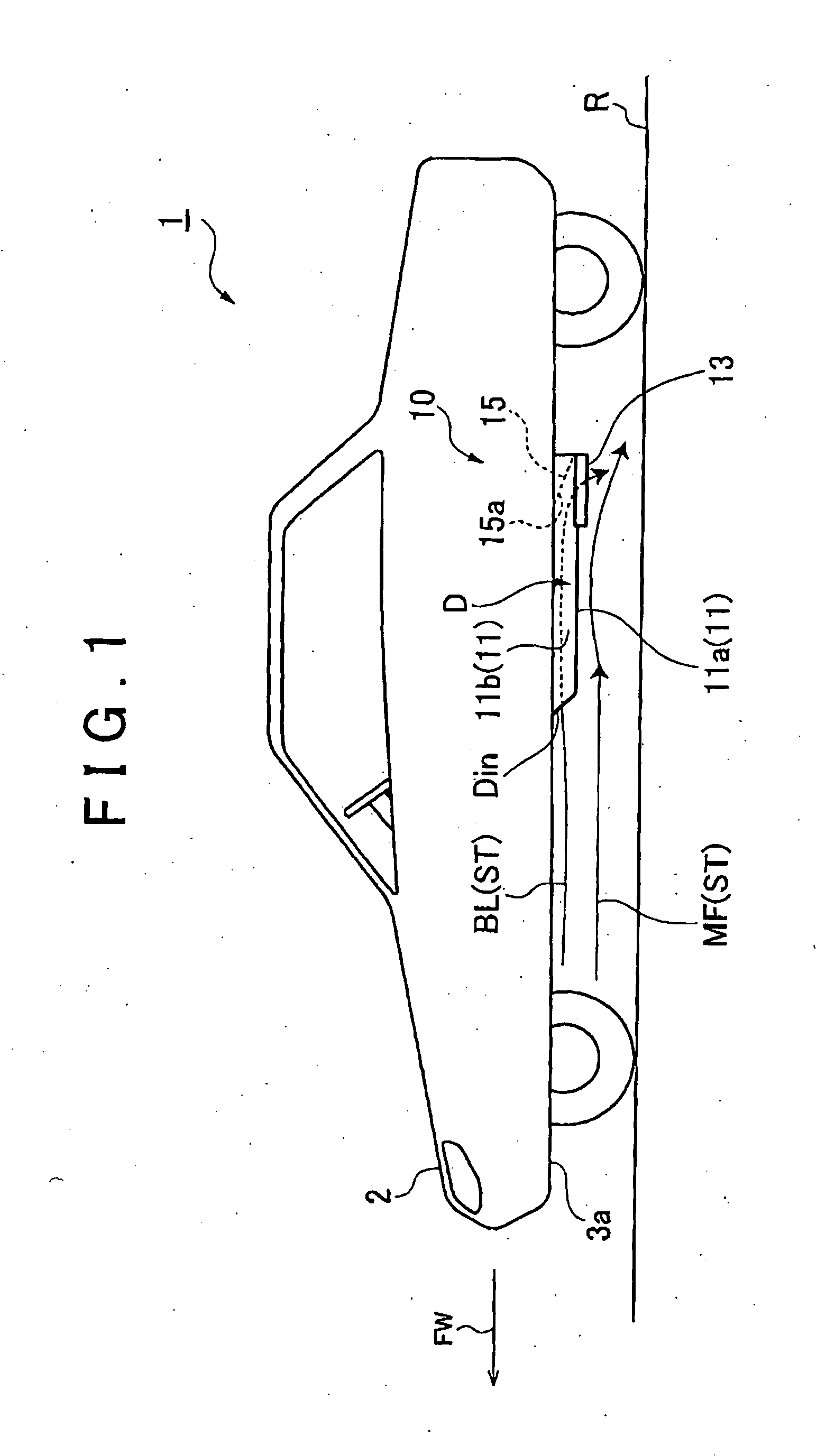
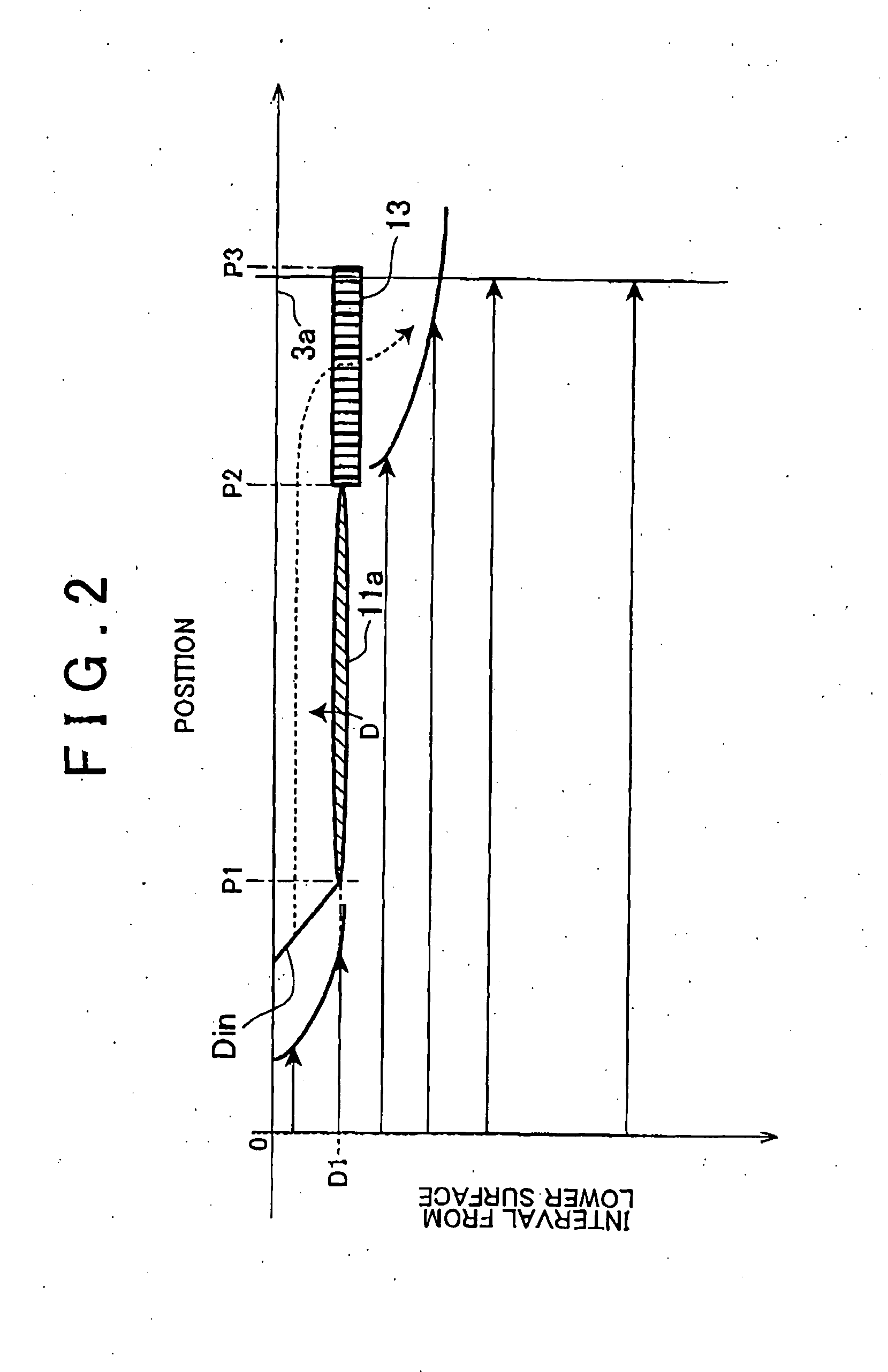
[0019]FIG. 1 is a schematic configuration diagram of a moving body in which a fluid control apparatus in accordance with the present invention is installed. As shown in FIG. 1, the fluid control apparatus 10 is an apparatus installed in a moving body 1. The fluid control apparatus 10 is an apparatus for separating an air stream ST generated around the moving body 1 due to movement of the moving body 1 into a main flow MF (simply referred to as “main flow MF” hereinafter) of the air stream ST and a boundary layer BL (simply referred to as “boundary layer BL” hereinafter) of the air stream ST. Here, the main flow MF is an air flow contained in the air stream ST, which has a uniform flow velocity at approximately the same speed as the moving speed of the moving body 1. Further, the boundary layer BL is an air flow contained in the air stream ST, which is formed around a surface of the moving body 1 and has a lower flow velocity than the main flow MF.
[0020]The fluid control apparatus 10...
second embodiment
[0034]FIG. 4 is a schematic configuration diagram of a moving body in which a fluid control apparatus in accordance with the present invention is installed. As shown in FIG. 4, the fluid control apparatus 20 is an apparatus installed in a moving body 1A. Further, the fluid control apparatus 20 is an apparatus for separating the air stream ST generated around the moving body 1A due to movement of the moving body 1A into the main flow MF and the boundary layer BL. The fluid control apparatus 20 is provided on the lower surface 3a (surface) of the body 2 of the moving body 1A such as a vehicle. The fluid control apparatus 20 includes a boundary layer separation portion 21, the duct D, a compression portion 27, and a blow-out portion 23. In the descriptions made hereinafter, up and down, front and rear, and left and right of the fluid control apparatus 20 represent the directions in the case that the body 2 side is up, the road surface R side is down, the traveling direction FW side is ...
PUM
 Abstract
Description
Claims
Application Information
 - R&D
- Intellectual Property
- Life Sciences
- Materials
- Tech Scout
- Unparalleled Data Quality
- Higher Quality Content
- 60% Fewer Hallucinations
Browse by: Latest US Patents, China's latest patents, Technical Efficacy Thesaurus, Application Domain, Technology Topic, Popular Technical Reports.
© 2025 PatSnap. All rights reserved.Legal|Privacy policy|Modern Slavery Act Transparency Statement|Sitemap|About US| Contact US: help@patsnap.com


