Illumination optical system and projector comprising the same
- Summary
- Abstract
- Description
- Claims
- Application Information
AI Technical Summary
Benefits of technology
Problems solved by technology
Method used
Image
Examples
Embodiment Construction
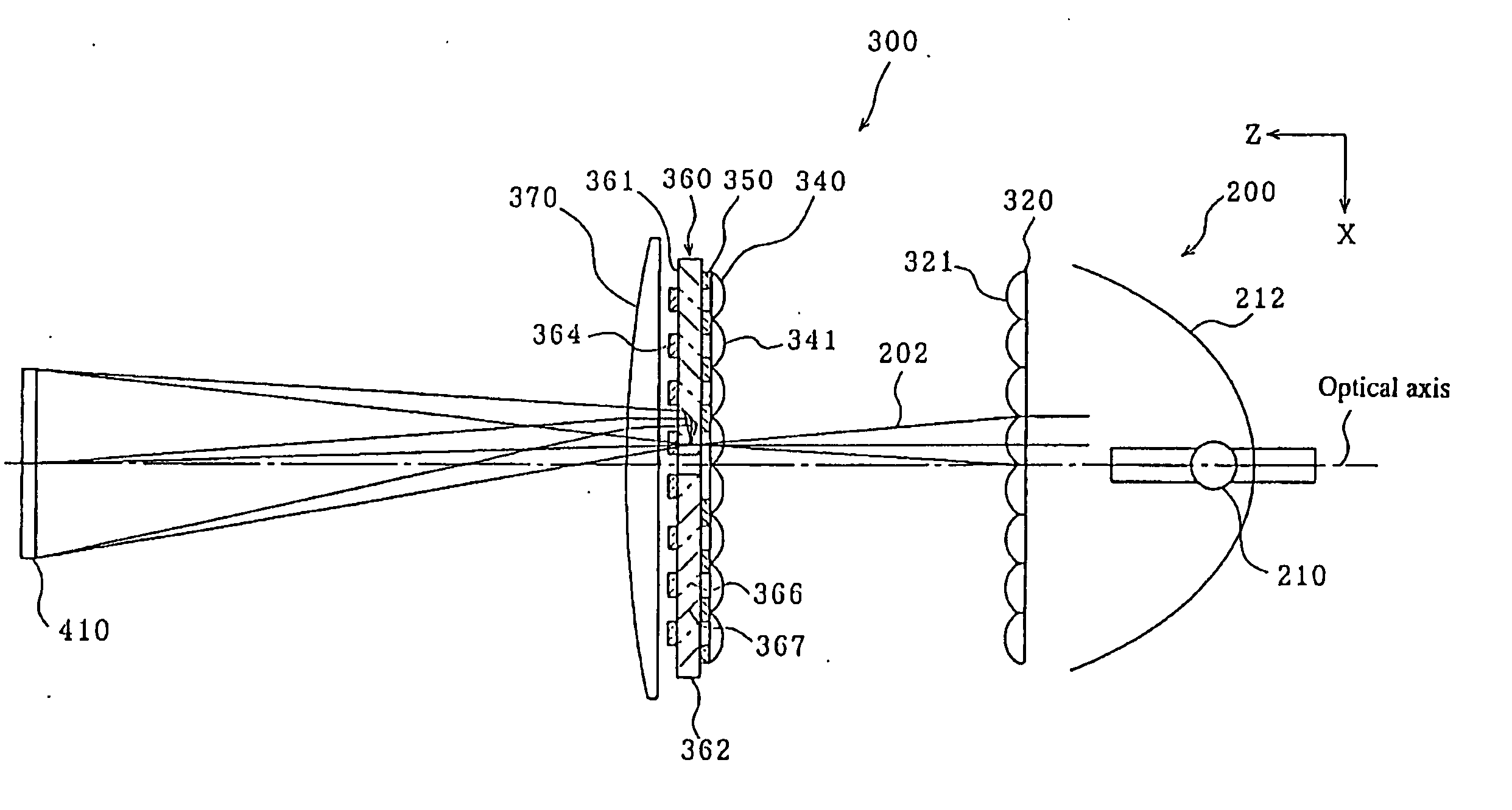
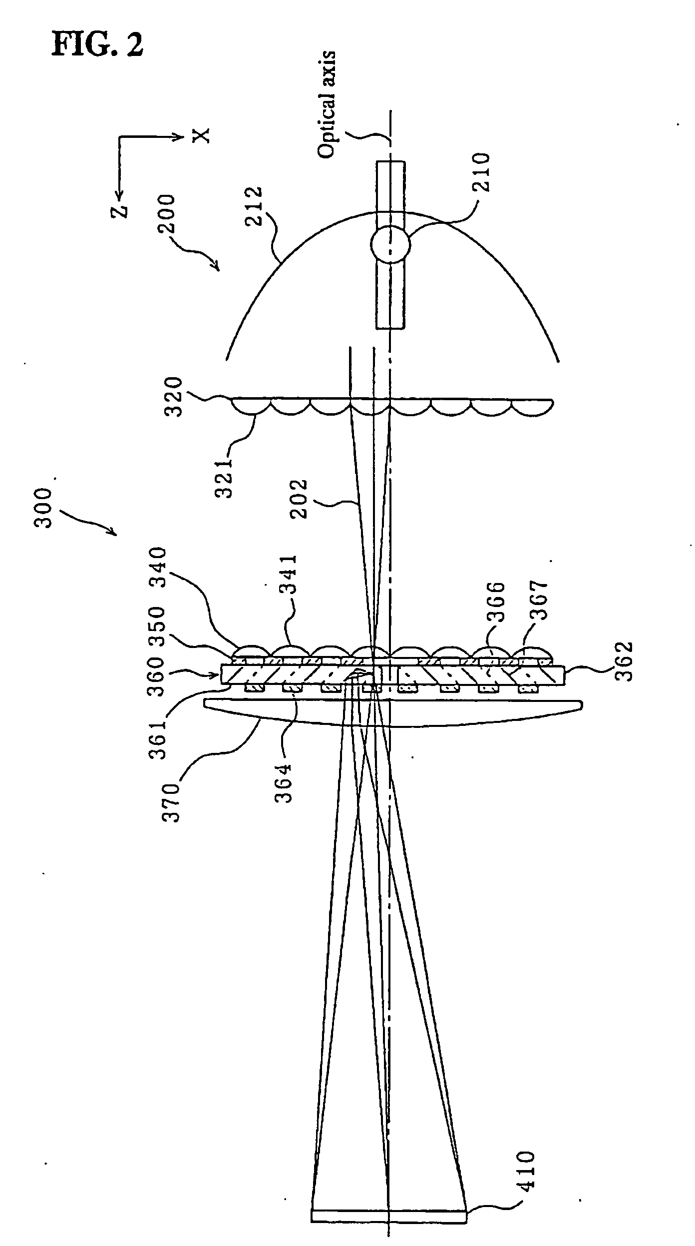
[0032] Now, embodiments of the present invention will be explained below by way of example. In the following explanations, the traveling direction of the light is defined as a z-direction, the direction of 12 o'clock with respect to the z-direction is defined as a y-direction, and the direction of 3 o'clock with respect to the z-direction is defined as a x-direction, unless otherwise specified.
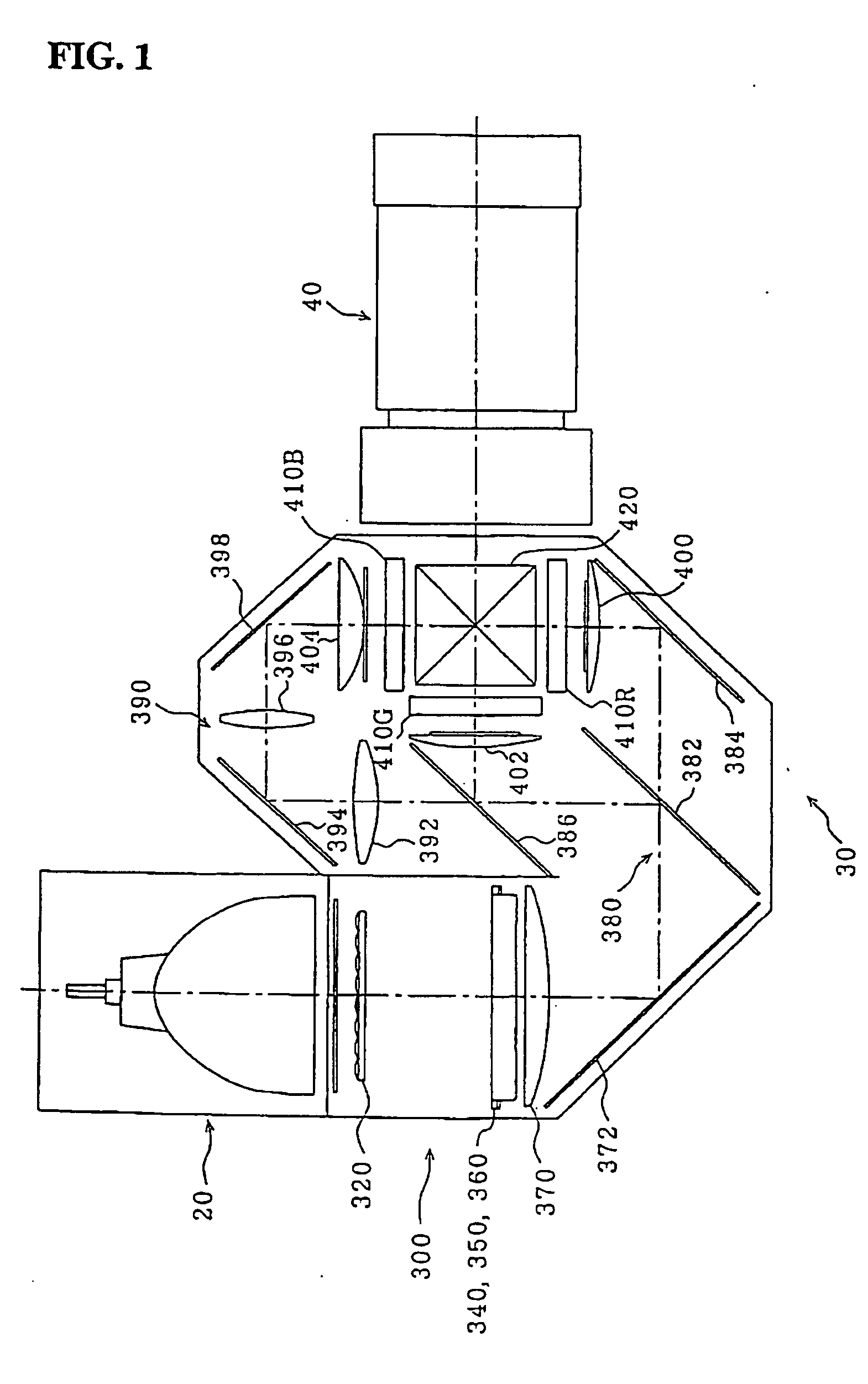
[0033]FIG. 1 is a schematic plan view showing the configuration of an illumination optical system incorporated into a projector according to an embodiment of the present invention. The optical system includes three main portions: a light source unit 20, an optical unit 30, and a projection lens 40. The optical unit 30 is provided with an integrator optical system 300 described later, a color beam splitting optical system 380 having dichroic mirrors 382, 386 and a reflective mirror 384, a relay optical system 390 having an incident lens 392, a relay lens 396 and reflective mirrors 394, 398. Th...
PUM
 Abstract
Description
Claims
Application Information
 - R&D
- Intellectual Property
- Life Sciences
- Materials
- Tech Scout
- Unparalleled Data Quality
- Higher Quality Content
- 60% Fewer Hallucinations
Browse by: Latest US Patents, China's latest patents, Technical Efficacy Thesaurus, Application Domain, Technology Topic, Popular Technical Reports.
© 2025 PatSnap. All rights reserved.Legal|Privacy policy|Modern Slavery Act Transparency Statement|Sitemap|About US| Contact US: help@patsnap.com


