Downhole zone isolation system

a technology of isolation system and downhole, which is applied in the direction of drinking water installation, well accessories, borehole/well accessories, etc., can solve the problems of preventing the removal of such valves and the problem of the screen assembly being problemati

Active Publication Date: 2006-01-10
BAKER HUGHES INC
View PDF23 Cites 75 Cited by
  • Summary
  • Abstract
  • Description
  • Claims
  • Application Information

AI Technical Summary

Benefits of technology

[0016]FIGS. 11-14 are an alternate to FIGS. 1-5 allowing returns by raising the concentric pipe instead of using

Problems solved by technology

The close fit of these sliding sleeves to the screen and the integral construction did not allow for alternate access to the formation if such valves refused to open.
Additionally, the integral construction with the screen sections precluded removal o

Method used


Image

  • Downhole zone isolation system
  • Downhole zone isolation system
  • Downhole zone isolation system

Examples


Embodiment Construction

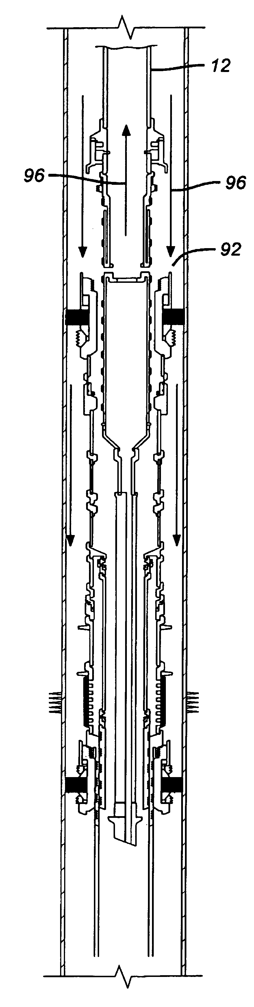
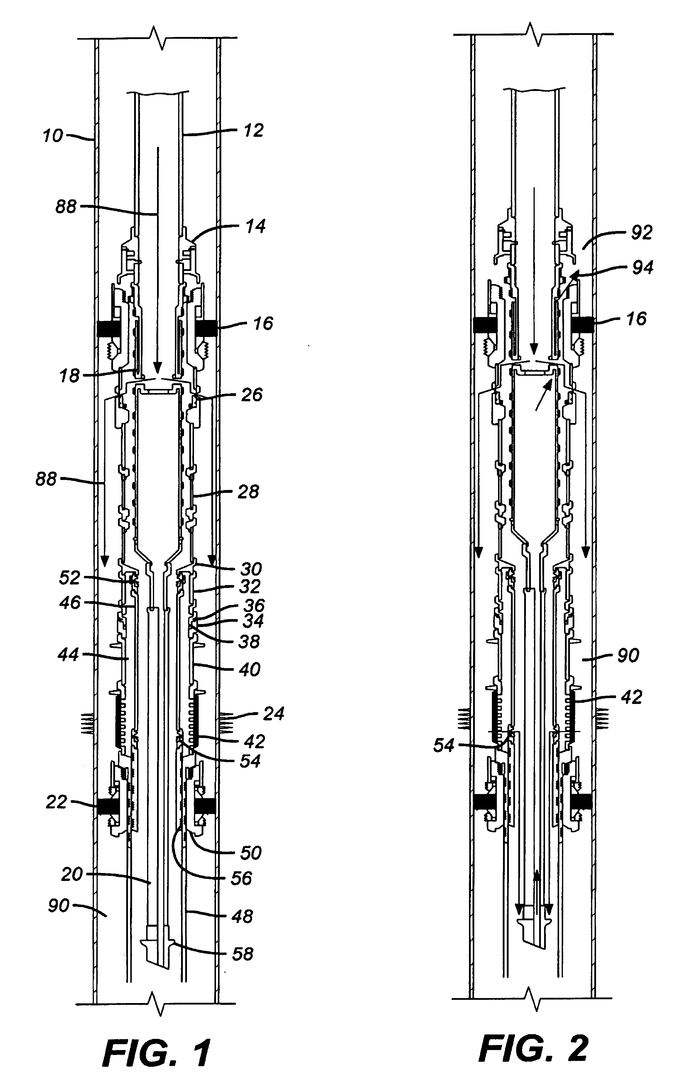
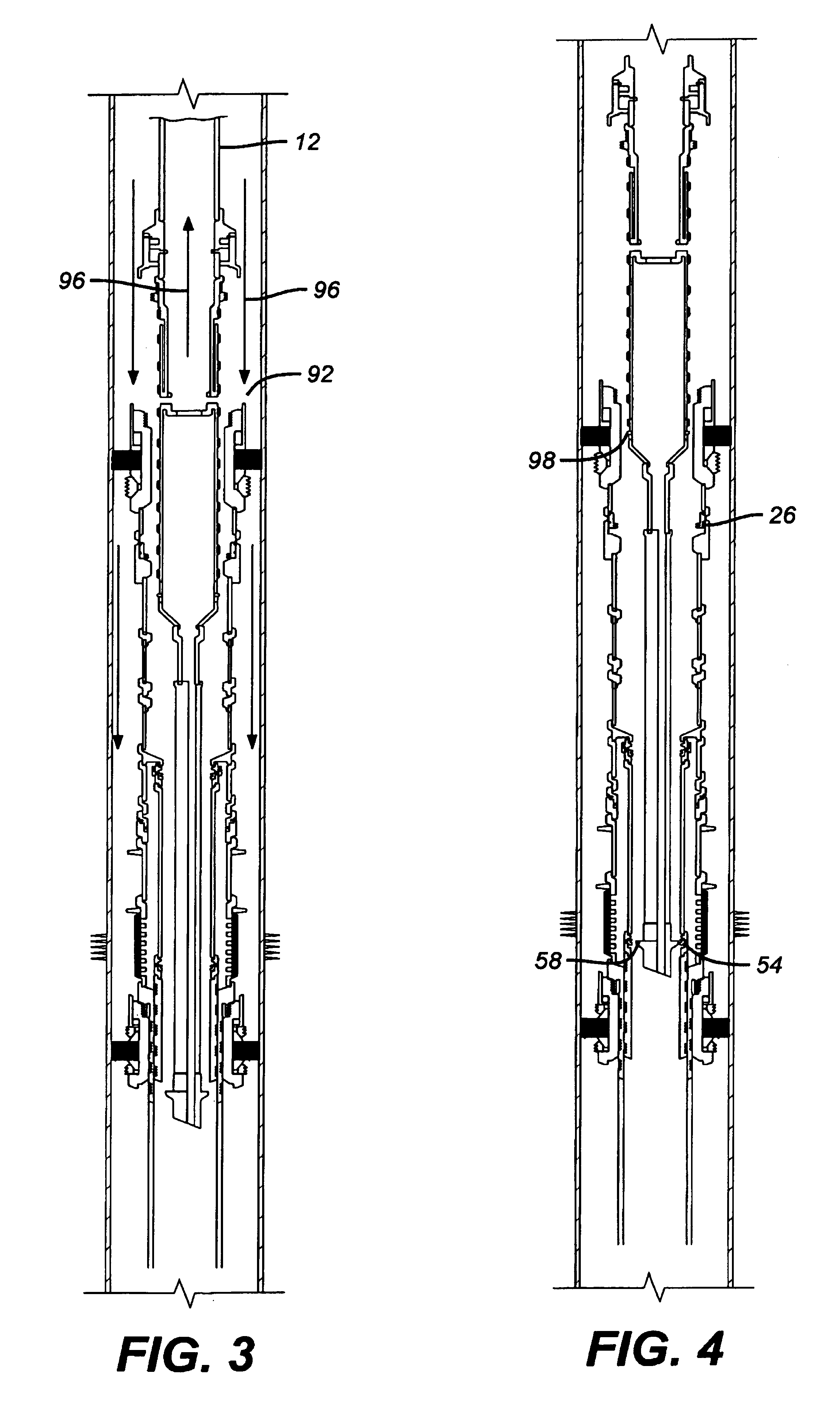
[0017]The gravel packing assembly of the present invention is illustrated in FIG. 1. A cased wellbore 10 is illustrated with a run in string 12 supporting a setting tool 14 to actuate the packer 16. A crossover tool 18 is supported from the setting tool 14 and a wash pipe 20 is, in turn, supported off the crossover tool 18. Down below is a sump packer 22 that has earlier been set in the well, generally before perforations 24 have been made, using a perforating gun of a type well known in the art.

[0018]Suspended from the isolation packer 16 is a frac sleeve valve 26, which is run in the open position. Below the sleeve valve 26 are tubulars or blank pipe 28 followed by a two-pin sub 30. The external assembly connected to the two pin sub 30 comprises a tubular 32 followed by a breakaway coupling 34 (seen more easily in the enlarged view in FIG. 8). Shear pin 36 holds coupling 34 together and seal 38 prevents leakage, when the coupling 34 is intact. Below coupling 34 are additional tubu...


PUM


Abstract

A gravel packing system featuring pressure actuated sliding sleeve valves mounted to an exterior annulus around a blanking pipe for screen sections is disclosed. An internal sliding sleeve valve is provided for subsequent closure of access through the screens. The presence of the annulus between the blanking pipe and the screen permits a backup access through perforating the blanking pipe while not damaging the screen. The sliding sleeve valves that are mounted internally and externally on the blanking pipe are removable apart from the screen section that already has gravel packed around it, if they fail to operate and need repair.

Description

PRIORITY INFORMATION[0001]This application claims the benefit of U.S. Provisional Application No. 60 / 370,911 on Apr. 8, 2002.FIELD OF THE INVENTION[0002]The field of this invention is downhole gravel packing systems with valves to isolate or allow access to various zones.BACKGROUND OF THE INVENTION[0003]Typically in a gravel pack completion, a sump packer is set in the wellbore and the formation is perforated. The perforating gun is removed and a gravel packing assembly is installed. Screens are part of this assembly as is a crossover tool. The crossover tool is secured to a production packer. The production packer is set and the crossover is configured in a manner so as to allow pumping gravel through the production packer and into the annular space outside the screens. Return fluid, less the deposited gravel, goes through the production screen and through a valve in a blank pipe in the screen, back through the crossover and out the annular space above the set production packer. A ...

Claims


Application Information

Patent Timeline
IPC IPC(8): E21B43/08E21B34/14E21B43/04
CPCE21B34/14E21B43/045E21B2034/007E21B2200/06
Inventor ZUKLIC, STEPHEN N.WOMBLE, ALLEN W.SCHEXNAYDER, JR., WILFREDCORBETT, GARYXU, RICHARD Y.ROTHERS, DAVIDROTH, BRIANLOUVIERE, RUSSELL T.
Owner BAKER HUGHES INC
Why Eureka
Try Eureka