Bone plate stabilization system and method for its use

a technology bone plate, which is applied in the field of bone plate stabilization system, can solve the problems of abnormal angulation or slippage of the spine, affecting the structure and function of the spinal column, and experiencing extreme and debilitating pain

Active Publication Date: 2006-01-10
RSB SPINE
View PDF16 Cites 285 Cited by
  • Summary
  • Abstract
  • Description
  • Claims
  • Application Information

AI Technical Summary

Problems solved by technology

Various types of problems can affect the structure and function of the spinal column.
In addition congenital or acquired deformities can cause abnormal angulation or slippage of the spine.
Patients who suffer from one of more of these conditions often experience extreme and debilitating pain, and can sustain permanent neurologic damage if the conditions are not treated appropriately.
However, there are disadvantages to the present stabilization devices.
Loss of alignment during the healing phase can cause a poor outcome for the patient.
The device must be secure in its attachment to the spine to prevent migration of the implant or backout of the screws from the bone which could result in damage to the structures surrounding the spine, resulting in severe and potentially life threatening complications.
This device is difficult to place, and overpenetration of the screws can result in damage to the spinal cord.
Problems have resulted from over ridged fixation and stress shielding, resulting in nonunion of the bony fusion, chronic micromotion during healing resulting in stress fracture of the fixation device at either the screw or the plate, insecure locking of the screw to the plate resulting in screw backout, or inadequate fixation strength and resultant collapse of the graft and angulation of the spine.
Because these devices are typically bridged across the bone, for example in the cervical region, they occasionally aggravate the esophagus, making it difficult for one to swallow food.
Local angularity in the vertebral column often causes high shearing stresses to be applied to the screws.
These stresses may fatigue the screws or cause deformation of the screw holes.

Method used


Image

  • Bone plate stabilization system and method for its use
  • Bone plate stabilization system and method for its use
  • Bone plate stabilization system and method for its use

Examples


Embodiment Construction

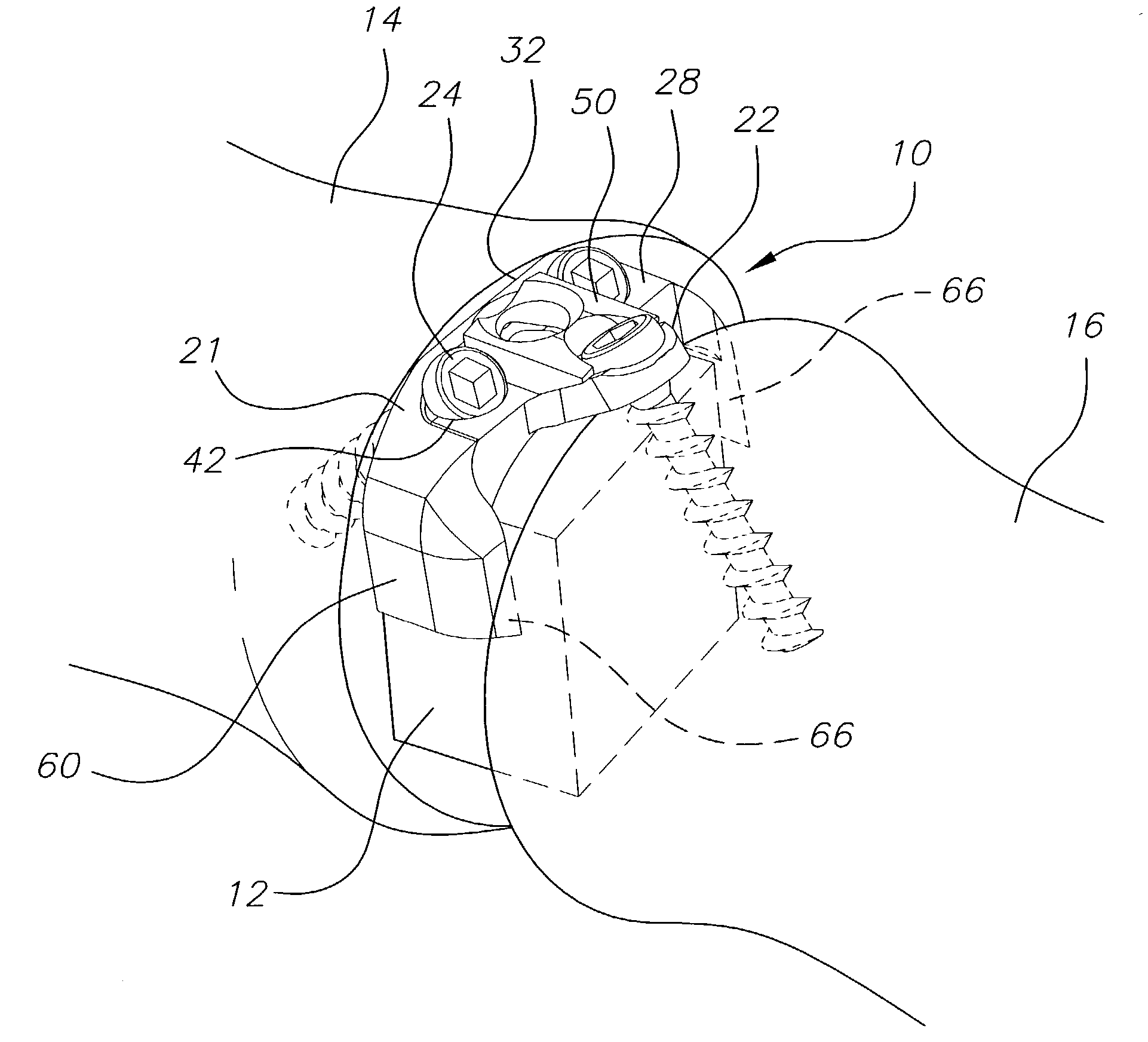
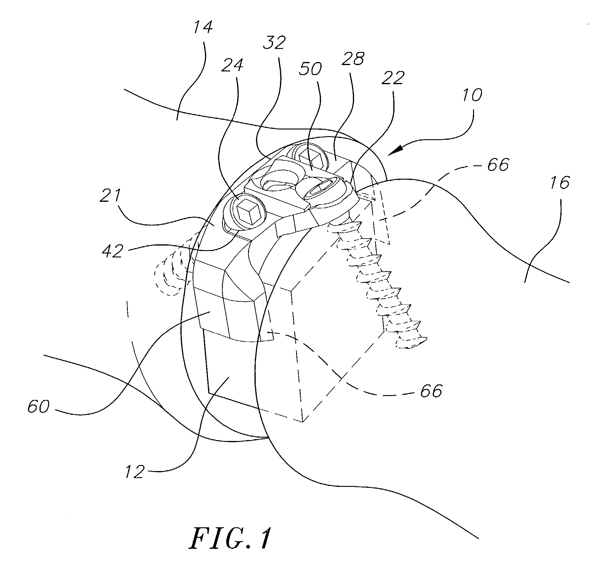
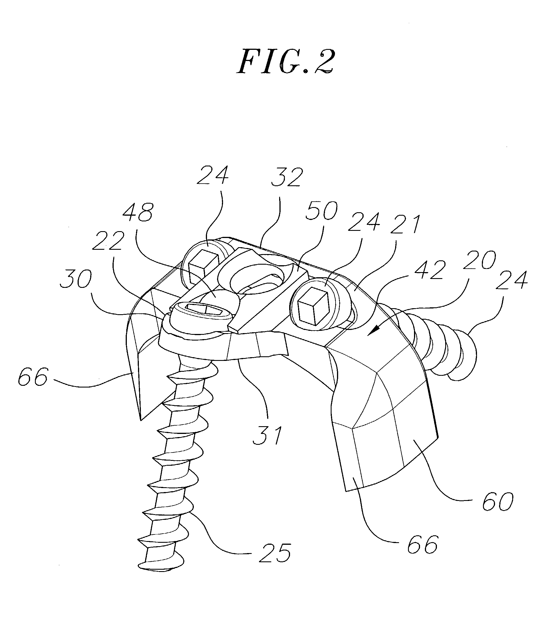
[0020]The present invention is directed to a bone stabilization plate system for stabilizing two adjacent bones (including bone fragments), such as adjacent vertebral bodies, while they heal, as well as to methods for its use. A particularly preferred bone stabilization plate system 10 constructed in accordance with the present invention is shown in FIGS. 1 to 4. The depicted bone stabilization plate system comprises a base plate 20 having first and second ends, and including a primary member 21 and a secondary member 22 at the second end of the base plate. The secondary member 22 is angled relative to the primary member 21, as discussed further below, although other designs are contemplated within the scope of the invention.

[0021]The base plate 20 may be made of any suitable material, and is preferably made from titanium or a titanium alloy. The thickness of the base plate 20 is not critical, and preferably ranges from about 1 mm to about 2 mm, and more preferably is about 1.6 mm. ...


PUM


Abstract

A method for joining first and second bones is provided. The method comprises inserting between the side surfaces of the bones a base plate having a first end nearer the first bone and a second end nearer the second bone. The base plate has a first screw hole extending through the first end and a second screw hole extending through the second end. A first bone screw is introduced through the first screw hole and into the first bone. The first bone screw is introduced at an angle relative to the top surface of the bone ranging from about 20° to about 60°. A second bone screw is introduced through the second screw hole and into the second bone. The second bone screw is introduced at an angle relative to the top surface of the bone ranging from about 20° to about 70°. At least a part of the first bone screw and at least a part of the second bone screw are covered to prevent the first and second bone screws from backing out of the first and second bones, respectively.

Description

FIELD OF THE INVENTION[0001]The present invention is directed to a bone plate system that is particularly useful for assisting with the surgical arthrodesis (fusion) of two bones together, and more particularly, to a bone plate that provides and controls limited movement between the bones during fusion.BACKGROUND[0002]The spinal column of vertebrates provides support to bear weight and protection to the delicate spinal cord and spinal nerves. The spinal column comprises a series of vertebrae stacked on top of each other. There are typically seven cervical (neck), twelve thoracic (chest), and five lumbar (low back) segments. Each vertebra has a cylindrical shaped vertebral body in the anterior portion of the spine with an arch of bone to the posterior which covers the neural structures. Between each vertebral body is an intervertebral disk, a cartilaginous cushion to help absorb impact and dampen compressive forces on the spine. To the posterior the laminar arch covers the neural str...

Claims


Application Information

Patent Timeline
Patent Type & Authority Patents(United States)
IPC IPC(8): A61B17/80A61B17/70A61F2/28A61F2/30A61F2/44
CPCA61B17/7059A61B17/8042A61F2/28A61F2002/30604A61F2002/2835A61F2002/30578A61F2/4455
Inventor BRAY, ROBERT S.
Owner RSB SPINE
Why Eureka
Try Eureka