Hydrogen passivation shut down system for a fuel cell power plant

a technology of hydrogen passivation and shut down system, which is applied in the direction of cell components, electrochemical generators, cell component details, etc., can solve the problems of inability to meet the requirements of the power plant,

Inactive Publication Date: 2006-01-10
AUDI AG
View PDF11 Cites 56 Cited by
  • Summary
  • Abstract
  • Description
  • Claims
  • Application Information

AI Technical Summary

Benefits of technology

[0011]In an additional embodiment, the system may include a hydrogen sensor that may be utilized to determine a concentration of hydrogen fuel within the anode and cathode flow paths while the fuel cell power plant is shut down. If the sensor detects that the hydrogen concentration has declined below acceptable limits, such as below 0.0001 percent hydrogen, a controller may open the hydrogen inlet valve to actively direct hydrogen to enter the anode and cathode flow paths, while the fuel cell power plant is shut down, such as immediately prior to a start up of the plant. Output from the sensor may also be used to select a start up procedure. An exemplary start up procedure includes a rapid fuel purge wherein the hydrogen fuel is directed to traverse an anode flow field of the fuel cell in less than 1.0 seconds, or preferably in less than 0.2 seconds, and most preferably in less than 0.05 seconds to minimize oxidation and corrosion of electrode catalyst and catalyst support materials. The hydrogen sensor may be a direct hydrogen concentration sensor known in the art, or a sensor circuit in electrical communication with the catalysts of the fuel cell.
[0012]The system may also include an anode recycle line and anode recycle blower secured in fluid communication between an anode exhaust and anode inlet of the anode flow path. The anode recycle line and blower may also be in fluid communication with the reducing fluid fuel storage source so that the anode recycle blower may rapidly move the hydrogen fuel through the anode flow path.
[0013]In a further embodiment, the anode flow path may include an anode exhaust vent, and the cathode flow path may include a cathode exhaust vent, wherein both the anode exhaust vent and cathode exhaust vent are located with reference to a directional force of gravity to be below the fuel cell. Because hydrogen is lighter than oxygen, the hydrogen will tend to remain above, or within the fuel cell while atmospheric oxygen entering the flow paths during shut down will tend to flow downward, out of the anode and cathode flow paths through the anode and cathode exhaust vents, thereby aiding in preserving a finite hydrogen concentration of greater than 0.0001 percent during shut down of the fuel cell power plant.

Problems solved by technology

In fuel cell power plants of the prior art, it is well known that, when an electrical circuit connected to the fuel cells is disconnected or opened and there is no longer a load across the cell, such as upon and during shut down of the cell, the presence of air on a cathode electrode along with hydrogen fuel remaining on an anode electrode, often cause unacceptable anode and cathode potentials, resulting in oxidation and corrosion of electrode catalyst and catalyst support materials and attendant cell performance degradation.
Further, the use of an inert gas purge avoided, on start-up, the possibility of the presence of a flammable mixture of hydrogen and air, which is a safety issue.
However, the costs and complexity of such stored inert gases are undesirable especially in automotive applications where compactness and low cost are critical, and where the system must be shut down and started up frequently.
However, it has been found that even with known solutions, the presence of oxygen within an anode flow field during start up results in a reverse current leading to unacceptable, localized electrode potentials and corrosion of catalysts and catalyst support materials.
Moreover, active addition of hydrogen to fuel cells of a power plant while the plant is shut down and unattended presents significant safety issues where a system failure may lead to release of potentially flammable hydrogen concentrations out of the power plant.

Method used


Image

  • Hydrogen passivation shut down system for a fuel cell power plant
  • Hydrogen passivation shut down system for a fuel cell power plant

Examples


Embodiment Construction

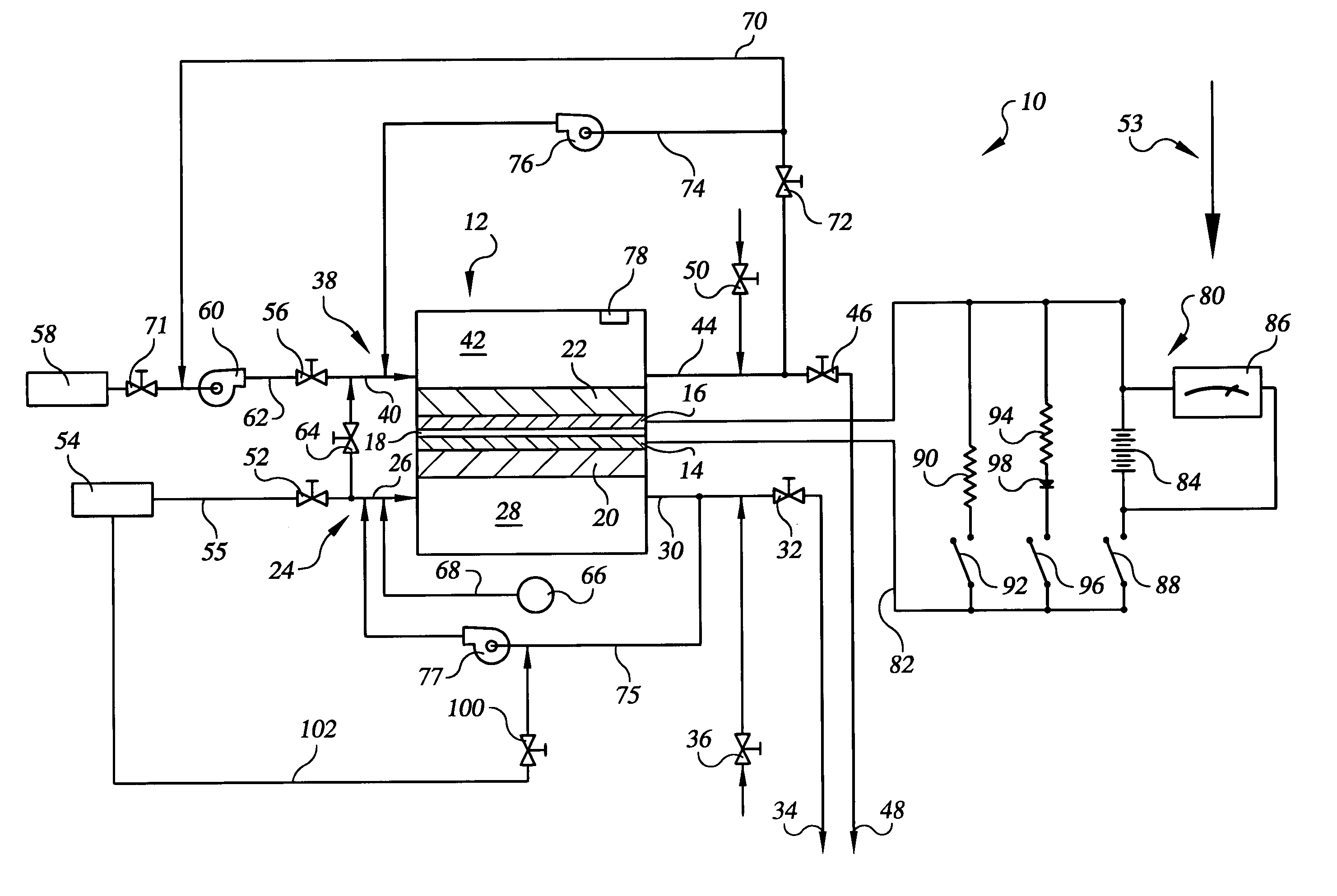
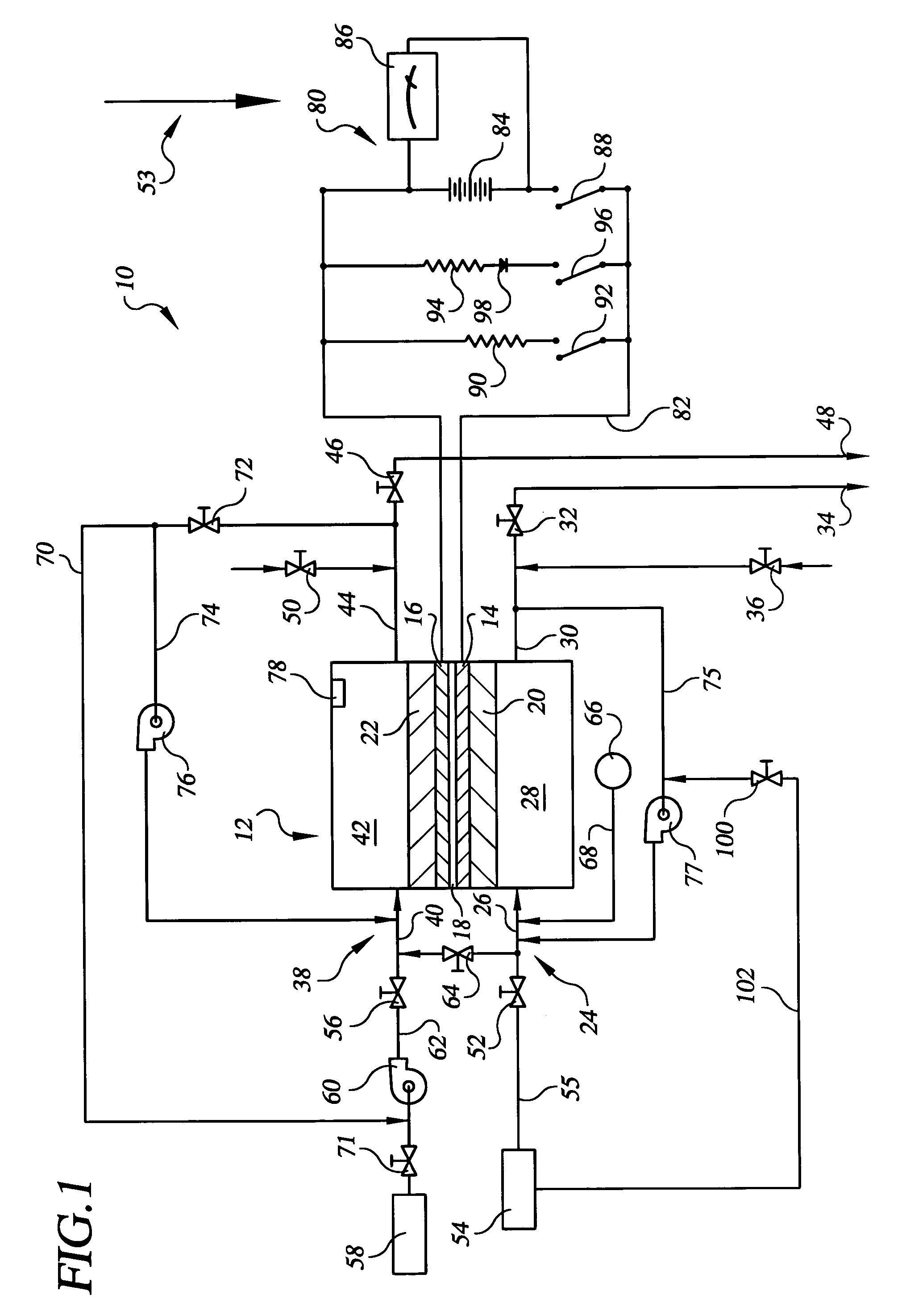
[0019]Referring to the drawings in detail, a first embodiment of a hydrogen passivation shut down system for a fuel cell power plant is shown in FIG. 1, and is generally designated by the reference numeral 10. The system 10 includes at least one fuel cell, such as a fuel cell 12 having an anode catalyst 14 (which may also be referred to herein as an anode electrode), a cathode catalyst 16 (which may also be referred to as a cathode electrode), and an electrolyte 18 disposed between the anode and cathode. The electrolyte 18 may be in the form of a proton exchange membrane (PEM) of the type described in U.S. Pat. No. 6,024,848, or the electrolyte may be held within a ceramic matrix, such as is typically found in acid aqueous electrolyte fuel cells, such as phosphoric acid electrolyte fuel cells.

[0020]The anode catalyst 14 may be supported on an anode substrate layer 20, and the cathode electrode 16 may be supported on a cathode substrate layer 22. The system 10 also includes an anode ...


PUM

PropertyMeasurementUnit
electrical currentaaaaaaaaaa
gravityaaaaaaaaaa
concentrationaaaaaaaaaa

Abstract

The invention is a hydrogen passivation shut down system for a fuel cell power plant (10). An anode flow path (24) is in fluid communication with an anode catalyst (14) for directing hydrogen fuel to flow adjacent to the anode catalyst (14), and a cathode flow path (38) is in fluid communication with a cathode catalyst (16) for directing an oxidant to flow adjacent to the cathode catalyst (16) of a fuel cell (12). Hydrogen fuel is permitted to transfer between the anode flow path (24) and the cathode flow path (38). A hydrogen reservoir (66) is secured in fluid communication with the anode flow path (24) for receiving and storing hydrogen during fuel cell (12) operation, and for releasing the hydrogen into fuel cell (12) whenever the fuel cell (12) is shut down.

Description

TECHNICAL FIELD[0001]The present invention relates to fuel cell power plants that are suited for usage in transportation vehicles, portable power plants, or as stationary power plants, and the invention especially relates to a system that minimizes performance degradation of fuel cells of the plant resulting from repeated shutting down and starting up of the plant.BACKGROUND ART[0002]Fuel cell power plants are well-known and are commonly used to produce electrical energy from hydrogen containing reducing fluid fuel and oxygen containing oxidant reactant streams to power electrical apparatus such as power plants and transportation vehicles. In fuel cell power plants of the prior art, it is well known that, when an electrical circuit connected to the fuel cells is disconnected or opened and there is no longer a load across the cell, such as upon and during shut down of the cell, the presence of air on a cathode electrode along with hydrogen fuel remaining on an anode electrode, often ...

Claims


Application Information

Patent Timeline
Patent Type & Authority Patents(United States)
IPC IPC(8): H01M8/00H01MH01M2/00H01M2/02H01M2/14H01M8/04H01M8/18
CPCH01M8/04097H01M8/04201H01M8/04216H01M8/04231H01M8/04447H01M8/04559H01M8/04567H01M8/04753H01M8/04955H01M2008/1095Y02E60/50H01M8/04303H01M8/04228H01M8/0258H01M8/04H01M8/04225H01M8/04302
Inventor MARGIOTT, PAUL R.PRELI, JR., FRANCIS R.KULP, GALEN W.PERRY, MICHAEL L.REISER, CARL A.BALLIET, RYAN J.
Owner AUDI AG
Why Eureka
Try Eureka