Hydrogen passivation shut down system for a fuel cell power plant

Inactive Publication Date: 2009-09-03
UNITED TECH CORP +1
View PDF2 Cites 8 Cited by
  • Summary
  • Abstract
  • Description
  • Claims
  • Application Information

AI Technical Summary

Benefits of technology

[0013]In an additional embodiment, the system may include a hydrogen sensor that may be utilized to determine a concentration of hydrogen fuel within the anode and cathode flow paths while the fuel cell power plant is shut down. If the sensor detects that the hydrogen concentration has declined below acceptable limits, such as below 0.0001 percent hydrogen, a controller may open the hydrogen inlet valve to actively direct hydrogen to enter the anode and cathode flow paths, while the fuel cell power plant is shut down, such as immediately prior to a start up of the plant. Output from the sensor may also be used to select a start up procedure. An exemplary start up procedure includes a rapid fuel purge wherein the hydrogen fuel is directed to traverse an anode flow field of the fuel cell in less than 1.0 seconds, or preferably in less than 0.2 seconds, and most preferably in less than 0.05 seconds to minimize oxidation and corrosion of electrode catalyst and catalyst support materials. The hydrogen sensor may be a direct hydrogen concentration sensor known in the art, or a sensor circuit in electrical communication with the catalysts of the fuel cell.
[0014]In an alternative, low-pressure hydrogen generator embodiment of the passivation shut-down system, instead of the hydrogen reservoir, a low-pressure hydrogen generator directs a flow of low-pressure hydrogen from the generator to the anode flow path downstream from the hydrogen inlet valve. The low-pressure hydrogen generator may be any generator capable of generating low-pressure hydrogen, such as an electrolysis cell powered by a direct current (“D.C.”) battery. During shutdown of the fuel cell a very small amount of hydrogen is necessary to maintain the fuel cell in a passive state to compensate for hydrogen leaking out of the fuel cell and / or penetration into the fuel cell of atmospheric oxygen that reacts with the hydrogen.
[0018]The system may also include an anode recycle line and anode recycle blower secured in fluid communication between an anode exhaust and anode inlet of the anode flow path. The anode recycle line and blower may also be in fluid communication with the reducing fluid fuel storage source so that the anode recycle blower may rapidly move the hydrogen fuel through the anode flow path.
[0019]In a further embodiment, the anode flow path may include an anode exhaust vent, and the cathode flow path may include a cathode exhaust vent, wherein both the anode exhaust vent and cathode exhaust vent are located with reference to a directional force of gravity to be below the fuel cell. Because hydrogen is lighter than oxygen, the hydrogen will tend to remain above, or within the fuel cell while atmospheric oxygen entering the flow paths during shut down will tend to flow downward, out of the anode and cathode flow paths through the anode and cathode exhaust vents, thereby aiding in preserving a finite hydrogen concentration of greater than 0.0001 percent during shut down of the fuel cell power plant.

Problems solved by technology

In fuel cell-power plants of the prior art, it is well known that, when an electrical circuit connected to the fuel cells is disconnected or opened and there is no longer a load across the cell, such as upon and during shut down of the cell, the presence of air on a cathode electrode along with hydrogen fuel remaining on an anode electrode, often cause unacceptable anode and cathode potentials, resulting in oxidation and corrosion of electrode catalyst and catalyst support materials and attendant cell performance degradation.
Further, the use of an inert gas purge avoided, on start-up, the possibility of the presence of a flammable mixture of hydrogen and air, which is a safety issue.
However, the costs and complexity of such stored inert gases are undesirable especially in automotive applications where compactness and low cost are critical, and where the system must be shut down and started up frequently.
An additional problem of fuel cell power plants that require frequent start-stop cycles, such as those used in transportation vehicles, is that, as a fuel cell power plant cools down to an ambient temperature after operation, a volume of gases within manifolds and flow fields, etc. within the plant necessarily decreases as the gases cool.
Also, a lot of gaseous water within the plant condenses to a liquid phase, resulting in a further decrease in the volume of the gases within the power plant.
This pressure differential causes wear on power plant valves and seals, and frequently leads to leaks of the atmosphere into fuel cell flow fields, which may in turn result in deleterious oxidation of electrode catalysts and catalysts support materials.
However, it has been found that even with known solutions, the presence of oxygen within an anode flow field during start up results in a reverse current leading to unacceptable, localized electrode potentials and corrosion of catalysts and catalyst support materials.
Moreover, active addition of hydrogen to fuel cells of a power plant while the plant is shut down and unattended presents significant safety issues where a system failure may lead to release of potentially flammable hydrogen concentrations out of the power plant.

Method used


Image

  • Hydrogen passivation shut down system for a fuel cell power plant
  • Hydrogen passivation shut down system for a fuel cell power plant
  • Hydrogen passivation shut down system for a fuel cell power plant

Examples


first embodiment

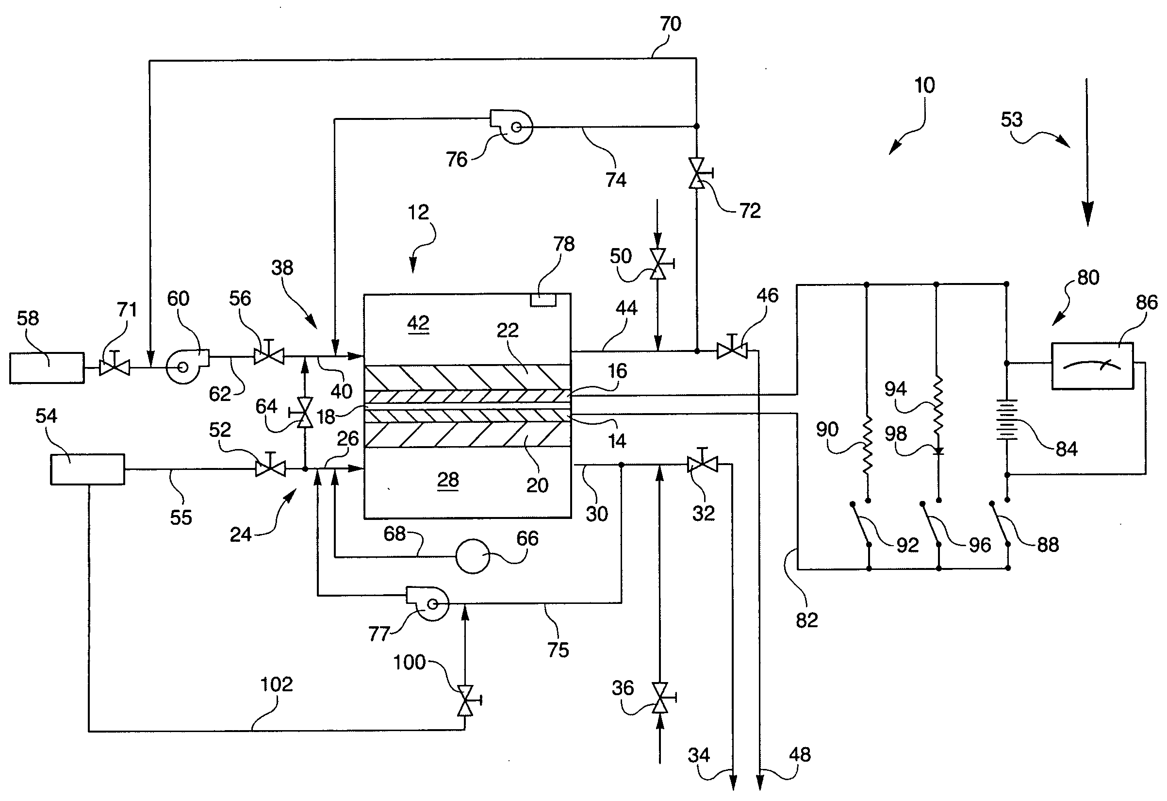
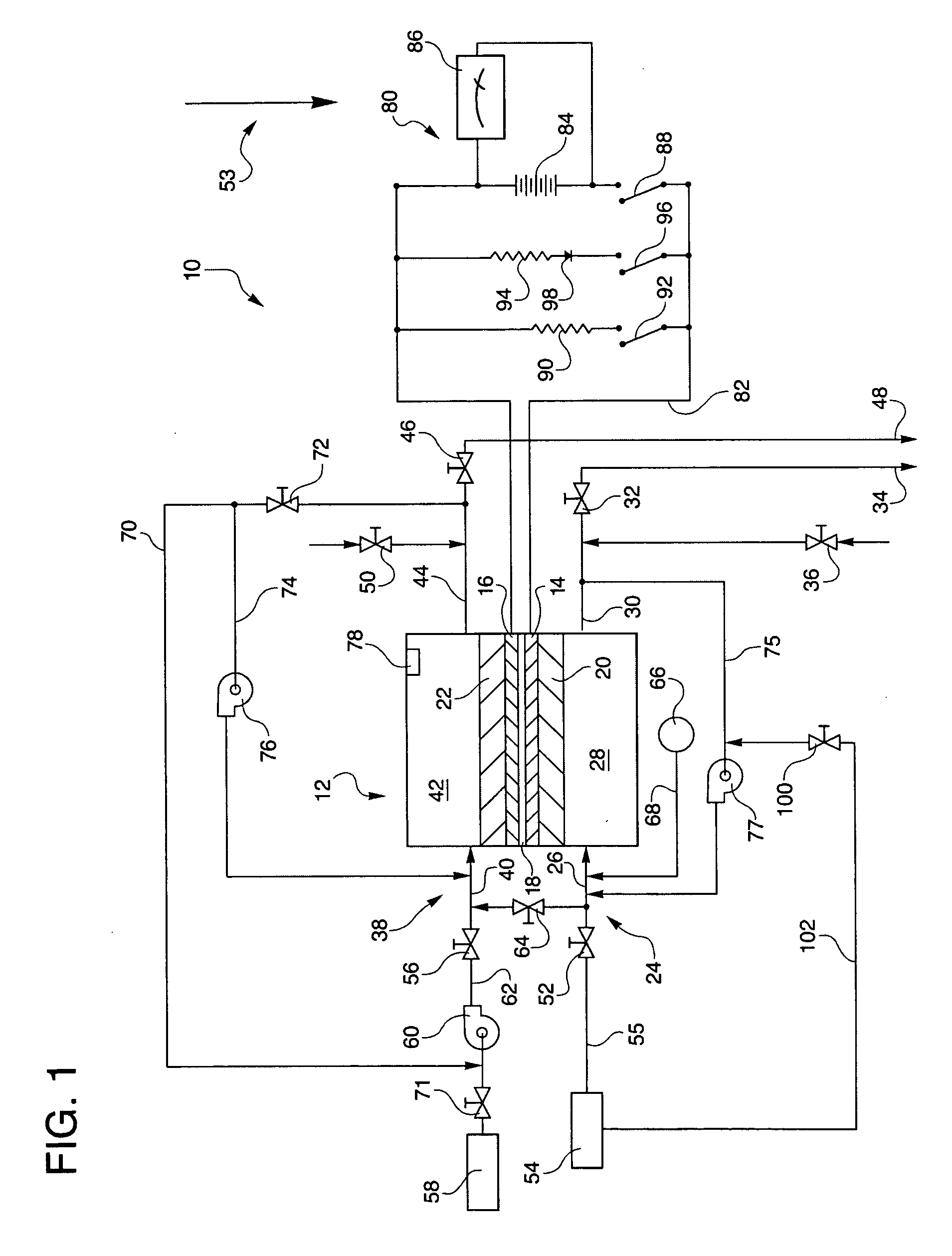
[0026]Referring to the drawings in detail, a hydrogen passivation shut down system for a fuel cell power plant is shown in FIG. 1, and is generally designated by the reference numeral 10. The system 10 includes at least one fuel cell, such as a fuel cell 12 having an anode catalyst 14 (which may also be referred to herein as an anode electrode), a cathode catalyst 16 (which may also be referred to as a cathode electrode), and an electrolyte 18 disposed between the anode and cathode. The electrolyte 18 may be in the form of a proton exchange membrane (PEM) of the type described in U.S. Pat. No. 6,024,848, or the electrolyte may be held within a ceramic matrix, such as is typically found in acid aqueous electrolyte fuel cells, such as phosphoric acid electrolyte fuel cells.

[0027]The anode catalyst 14 may be supported on an anode substrate layer 20, and the cathode electrode 16 may be supported on a cathode substrate layer 22. The system 10 also includes an anode flow path 24 in fluid ...

embodiment 200

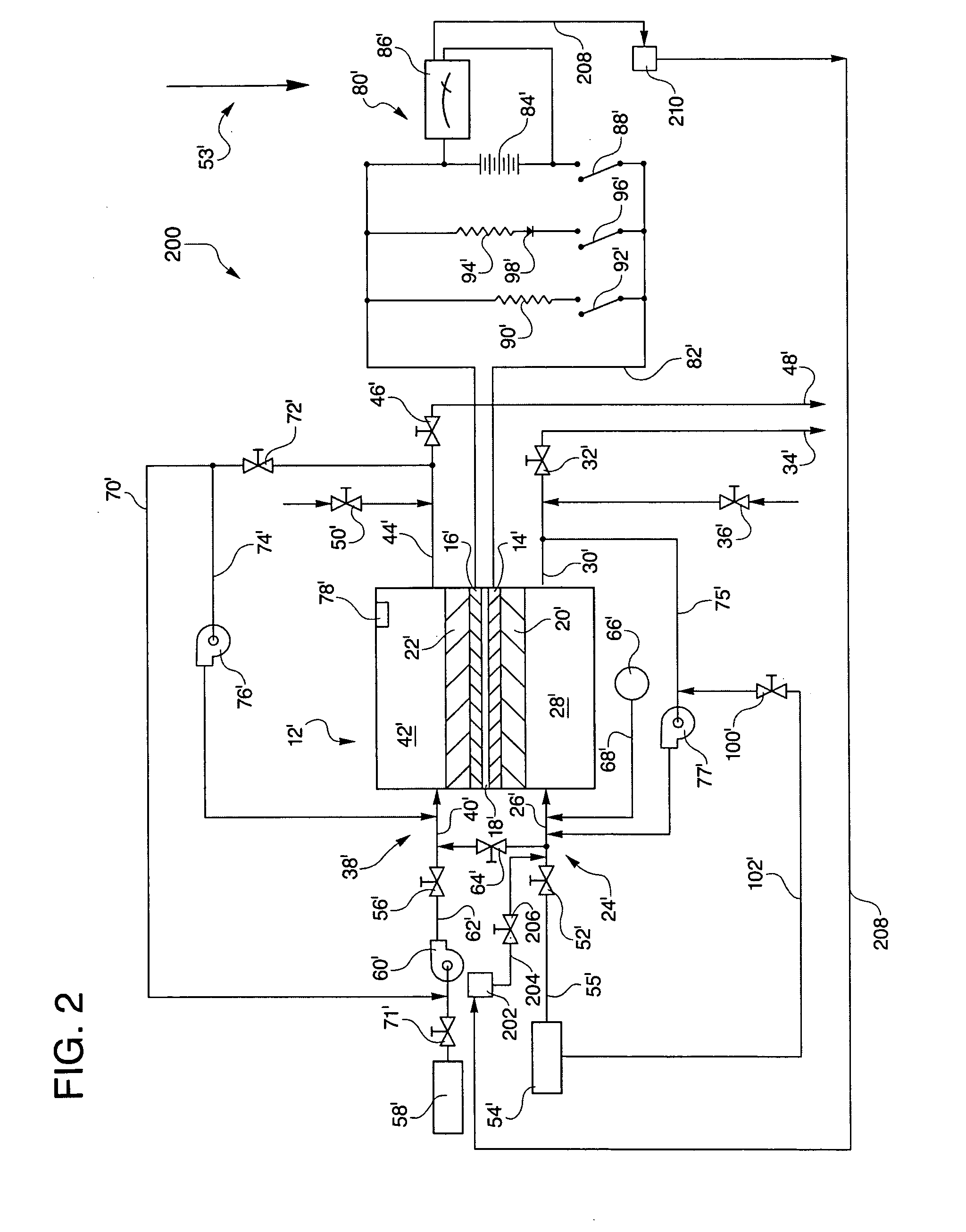
[0050]FIG. 2 shows a low-pressure hydrogen generator embodiment 200 of the hydrogen passivation shut down system. For purposes of convenience and efficiency, those components described above with respect to the FIG. 1 hydrogen passivation shut down system for a fuel cell power plant 10 that are virtually identical to comparable components in the low-pressure hydrogen generator embodiment 200 are shown in FIG. 2 as primes of the same components in FIG. 1, and where such FIG. 1 components are identical to FIG. 2 components, the components in FIG. 2 are not again described in detail. For example, the fuel cell 12 of FIG. 1, is shown as a fuel cell 12′ in FIG. 2.

[0051]The low-pressure hydrogen generator embodiment of the shutdown system 200 includes at least one fuel cell 12′ having the components described above regarding the fuel cell 12′ as shown in FIG. 1. Additionally, the low-pressure hydrogen generator embodiment includes a low-pressure hydrogen generator 202 for generating hydro...


PUM


Abstract

The invention is a hydrogen passivation shut down system for a fuel cell power plant (10, 200). During shut down of the plant (10, 200), hydrogen fuel is permitted to transfer between an anode flow path (24, 24′) and a cathode flow path (38, 38′) while a low-pressure hydrogen generator (202) selectively generates an adequate amount of hydrogen and directs flow of the low-pressure hydrogen into the fuel cell (12′) downstream from a hydrogen inlet valve (52′) to maintain the fuel cell (12′) in a passive state.

Description

CROSS REFERENCE TO RELATED APPLICATION[0001]This application is a continuation-in-part of U.S. patent application Ser. No. 11 / 978,270, filed on Oct. 29, 2007, which is a divisional application of U.S. patent application Ser. No. 11 / 284,867, filed on Nov. 22, 2005, which is a continuation application of U.S. patent application Ser. No. 10 / 635,779, filed on Aug. 6, 2003, which is now U.S. Pat. No. 6,984,464.TECHNICAL FIELD[0002]The present invention relates to fuel cell power plants that are suited for usage in transportation vehicles, portable power plants, or as stationary power plants, and the invention especially relates to a system that minimizes performance degradation of fuel cells of the plant resulting from repeated shutting down and starting up of the plant.BACKGROUND ART[0003]Fuel cell power plants are well-known and are commonly used to produce electrical energy from hydrogen containing reducing fluid fuel and oxygen containing oxidant reactant streams to power electrical ...

Claims


Application Information

Patent Timeline
IPC IPC(8): H01M8/04H01M8/18
CPCH01M8/04097H01M8/04201H01M8/04223H01M8/04447H01M8/04455H01M8/04552Y02E60/366H01M8/04761H01M8/0656H01M2008/1095C25B1/04Y02E60/50H01M8/04753Y02E60/36H01M8/04303H01M8/04228H01M8/043
Inventor REOSER, CARL A.SKIBA, TOMMYPATTERSON, JR., TIMOTHY
Owner UNITED TECH CORP
Why Eureka
Try Eureka