Method for calibrating an engraving amplifier

Inactive Publication Date: 2006-01-10
HELL GRAVURE SYST
View PDF10 Cites 0 Cited by
  • Summary
  • Abstract
  • Description
  • Claims
  • Application Information

AI Technical Summary

Benefits of technology

[0008]It is thus an object of the invention to improve a method for calibrating an engraving amplifier in an electronic engraving machine so as to shorten the time required for calibration, and to guarantee an automatic and optimal course of calibration to the greatest extent possible, without knowledge of the individual transmission functions and marginal conditions.
[0009]According to the present invention, a method is provided for calibrating an engraving amplifier in an electronic engraving machine for engraving printing cylinders for gravure printing. An engraving signal for actuating an engraving stylus of an engraving member is acquired from engraving values representing desired tone values and a periodic vibration signal in an engraving amplifier that can be adjusted by signal values for generating an engraving raster. With the engraving stylus, cells are engraved into the printing cylinder, the actual dimensions of the cells representing engraved actual tone values. Transmission functions are calculated which reproduce relationships between variations, which are adjusted at the engraving amplifier, of the signal values, and the resulting variations of the geometric actual dimensions of the engraved cells. Signal values for modifying at least one parameter “vibration”, “light”, “dark”, or “medium gradation” are set at the engraving amplifier. With the signal values, test cells are engraved for predetermined desired tone values, and their geometric actual dimensions are measured. Difference values are calculated from the actual dimensions and the desired dimensions of the cells upon consideration of the transmission functions. The signal values are corrected by adding the difference values. The steps of setting the signal values through correcting the signal values are repeated using the corrected signal values until the actual dimensions of the cells are at least within a tolerance range about the desired dimensions. To shorten the calibration time, in each sequence of the steps from setting the signal values through the correcting of the signal values, the actual dimensions of the cells are compared to the desired dimensions. If the actual dimensions are outside the tolerance range, transmission functions are recalculated. The difference values are computed upon consideration of the recalculated transmission functions. The signal values are corrected using the new difference values.

Problems solved by technology

A disadvantage of the conventional procedure is that the operator must have practical experience concerning the relationships between the electrical setting points and the actual geometric dimensions, which are to be expected, of the test cells, whereby numerous parameters and marginal conditions must be accounted for, such as the transmission behavior of the engraving amplifier and the engraving member, the cut angle and the degree of wear of the engraving stylus, as well as the material hardness of the surface of the printing cylinder that is to be engraved.
The known methods have the disadvantage that optimal calibration requires a relatively long time, since a new test engraving must always be conducted in the repetitions of the steps.

Method used


Image

  • Method for calibrating an engraving amplifier
  • Method for calibrating an engraving amplifier
  • Method for calibrating an engraving amplifier

Examples


Embodiment Construction

[0011]For the purposes of promoting an understanding of the principles of the invention, reference will now be made to the preferred embodiment illustrated in the drawings and specific language will be used to describe the same. It will nevertheless be understood that no limitation of the scope of the invention is thereby intended, such alterations and further modifications in the illustrated device, and / or method, and such further applications of the principles of the invention as illustrated therein being contemplated as would normally occur now or in the future to one skilled in the art to which the invention relates.

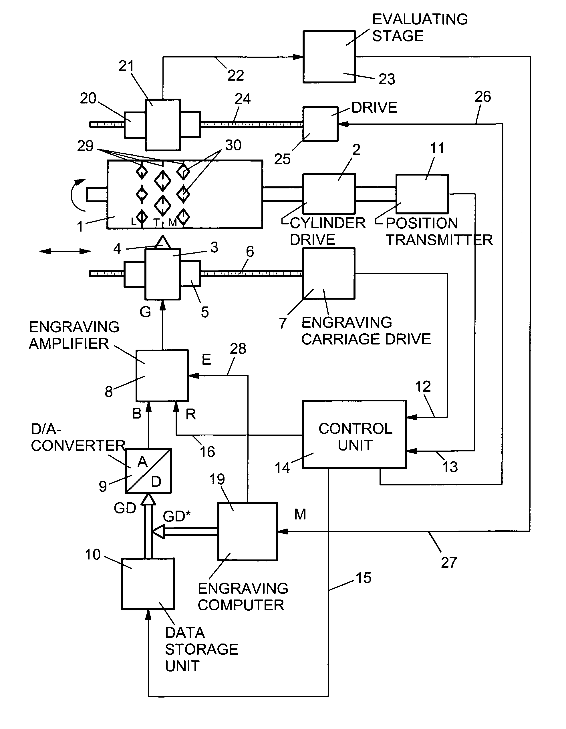
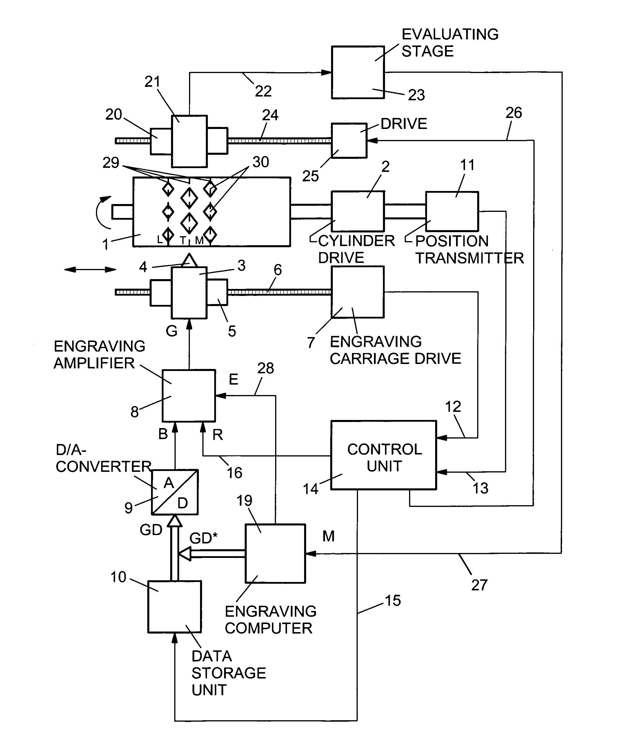
[0012]The preferred embodiment is detailed below with the aid of the FIGURE, which represents a principal exemplifying embodiment for an electronic engraving machine for engraving printing cylinders for gravure printing. The engraving machine is a HelioKlischograph® by Hell Gravure Systems GmbH, Kiel, DE.

[0013]A printing cylinder 1 is driven to rotate by a cylinder d...


PUM


Abstract

In a method for calibrating an engraving amplifier in an electronic engraving machine, whereby a vibration signal is used to control the engraving of an engraving element by using engraving tone values representing desired tone values ranging from “light” to “dark”, small cup shapes are engraved. The dimensions of the cup shapes define the real tone values. Transmission functions are initially determined, reproducing correlations between signal values that are adjusted in the engraving amplifier and the resulting changes in the real dimensions of the cup shapes. Sample cup shapes are engraved for predetermined desired tone values using the adjusted signal values for at least one of the parameters such as “vibration”, “light”, “dark” or “mid tone”. Differential values are obtained from real measured dimensions and the predetermined desired dimensions of the sample cup shapes, taking into account the transmission functions, whereby the differential values are used to correct the adjusted signal values. Operations are repeated using the corrected signal values until the real dimensions of the engraved cup shapes correspond to at least a permissible variation of the desired dimensions.

Description

BACKGROUND OF THE INVENTION[0001]The disclosure relates to the field of electronic reproduction technology and relates to a method for calibrating an engraving amplifier in an electronic engraving machine for engraving printing cylinders for gravure printing.[0002]In an electronic engraving machine, an engraving member with an engraving stylus as a cutting tool moves at a rotating printing cylinder in the axial direction. The engraving stylus, which is controlled by an engraving signal, cuts a series of cells into the surface of the printing cylinder. The engraving signal is formed in an engraving amplifier by superimposing image signal values with a periodic vibration signal. While the vibration signal effects an oscillating lifting motion of the engraving stylus for the purpose of generating the engraving raster, the image values which represent the tone values between “light” and “dark” which are to be reproduced determine the geometric dimensions of the engraved cells.[0003]So t...

Claims


Application Information

Patent Timeline
IPC IPC(8): H04N1/40B41C1/045H04N1/407
CPCH04N1/4078B41C1/045
Inventor WEIDLICH, ERMST-RUDOLF GOTTFRIED
Owner HELL GRAVURE SYST
Why Eureka
Try Eureka