
Ion generation apparatus used in ion implanter

Inactive Publication Date: 2005-11-17
SAMSUNG ELECTRONICS CO LTD
View PDF3 Cites 0 Cited by
  • Summary
  • Abstract
  • Description
  • Claims
  • Application Information

AI Technical Summary

Benefits of technology

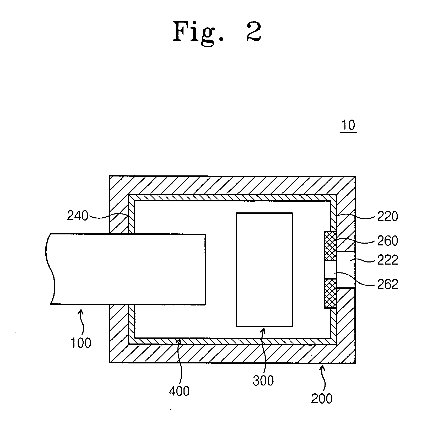
[0008] The present invention is directed to an ion implanting process which employs an ion generation apparatus that shortens the time required for cleaning a source chamber and thereby enhances the system operating rate. The ion implanting process is used for a semiconductor substrate. The process comprises providing the ion generation apparatus which comprises a source head for generating ions from a gas, and a source chamber including a manipulator for extracting only cations from the ions generated from the source head. The source chamber has an opening for supplying an extracted ion beam to a beam line portion. A liner is provided for surrounding the inner wall of the source chamber for preventing the ions from being deposited on an inner wall of the source chamber. Preferably, the liner is made of graphite. Moreover, the liner is preferably removable from the source chamber. The liner can also comprise a plurality of sections corresponding to the configuration of at least one of the inner walls of the source chamber. The plurality of the sections are disposed to allow the edges of adjacent sections to overlap one another. Preferably, each of the sections is fixed to the inner wall of the source chamber employing an attachment device.

Problems solved by technology

The energy and the uniformity of the ion beam varies with the arching, resulting in faulty process operation.
However, cleaning may not be fully complete if DI water is used.
Also, workers may encounter a risk of danger in the case where oxygenated water is used.
As previously stated, in the case where the worker scrubs an inner wall of a source chamber, a great deal of cleaning time is required which substantially lowers the effective operating rate of the system.

Method used


Image

  • Ion generation apparatus used in ion implanter
  • Ion generation apparatus used in ion implanter
  • Ion generation apparatus used in ion implanter

Examples


Embodiment Construction

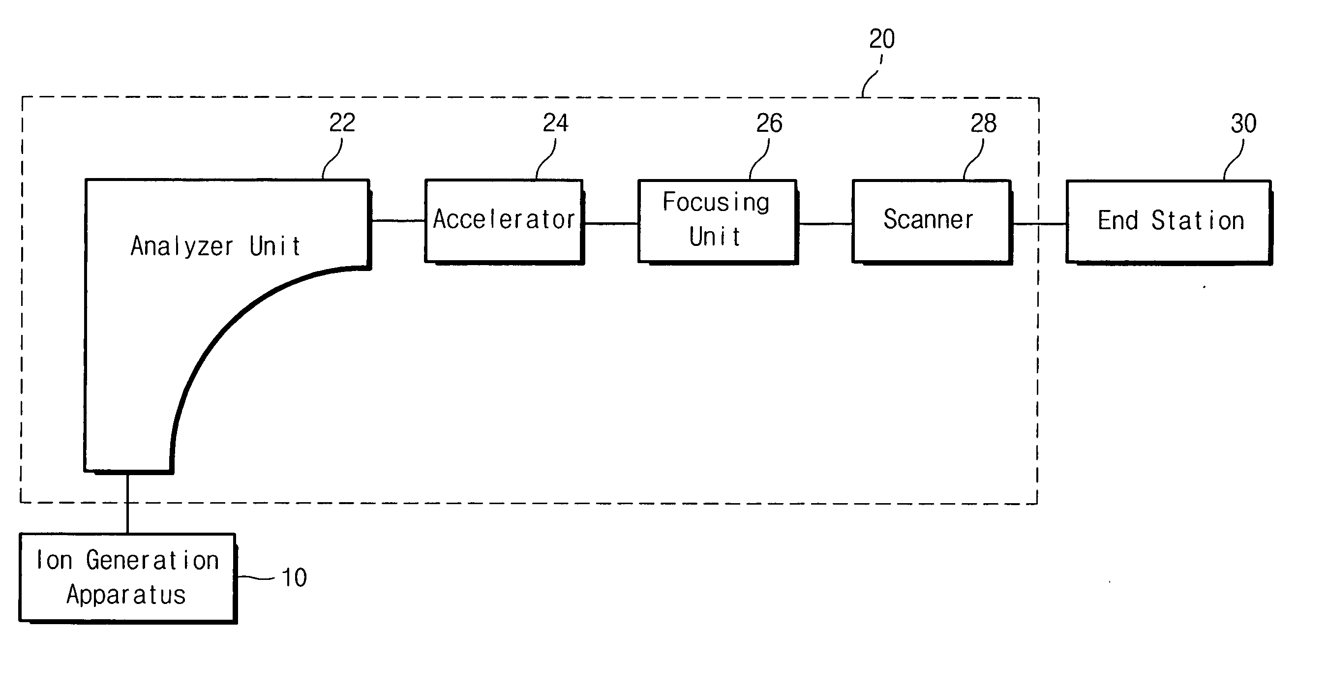
[0015] An ion implanter using an ion generation apparatus 10 according to the present invention is schematically illustrated in FIG. 1. The ion implanter includes the ion generation apparatus 10 for generating ion beam, a beam line assembly 20 where the ion beam is focused and accelerated, and an end station 30 where the ion beam is implanted to a wafer. The beam line assembly 20 includes an analyzer unit 22, an accelerator 24, a focusing unit 26, and a scanner 28. The analyzer unit 22 uses a mass analyzer to select desired-atomic-weight ions to be implanted to a wafer among the ions generated from the ion generation apparatus 10. The accelerator 24 accelerates the selected ions having energy to implant them up to a desired depth of a wafer. The focusing unit 26 focuses the ion beam to prevent the ion beam from being propagated due to a repulsive force when neutral ions are ionized to migrate. The scanner 28 changes a migration direction of the ion beam in an up-and-down and left-an...


PUM


Abstract

An ion generation apparatus used in an ion implanter includes a source head for generating ions and a source chamber with a manipulator for extracting only cations from the generated ions. A liner comprising a plurality of sections is installed at inner faces of the source chamber. An existing liner can be periodically replaced with a new liner to shorten a time required for cleaning the inner faces of the source chamber.

Description

PRIORITY STATEMENT [0001] This application claims priority of Korean Patent Application No. 2004-33591, filed on May 12, 2004 in the Korean Intellectual Property Office, the disclosure of which is incorporated herein in its entirety by reference. BACKGROUND OF THE INVENTION [0002] 1. Field of the Invention [0003] The present invention relates to an apparatus for manufacturing semiconductor devices and, more particularly, to an ion generation apparatus used in an ion implanter for implanting ions onto a wafer. [0004] 2. Description of Related Art [0005] Ion implantation involves p-type impurities such as boron (B), aluminum (Al), and indium (In) and n-type impurities such as stibium (Sb), phosphorus (P), and arsenic (As). These impurities are converted into an ion-beam-state. Then, they are implanted into semiconductor crystals to obtain desired-conduction-type and resistivity devices. The ion implantation has been used widely because the concentration of impurities implanted into a ...

Claims


Application Information

Patent Timeline
IPC IPC(8): H01J27/00H01L21/265H01J37/08
CPCH01J27/022H01J27/08H01J2237/082H01J2237/0213H01J2237/022H01J37/08A47J41/0044A47J41/0061A47J41/0083
Inventor NAM, SEUNG-MAN
Owner SAMSUNG ELECTRONICS CO LTD
Learn More