
Implantable heart monitors having flat capacitors with curved profiles

a technology of flat capacitors and heart monitors, which is applied in the field of flat electrolytic capacitors for use, can solve the problems of wasting space, gaps or voids between the cases and the housings, and incompatible walls of the cases with the rounded edges and corners of the implantable device housings

Inactive Publication Date: 2006-01-10
CARDIAC PACEMAKERS INC
View PDF169 Cites 45 Cited by
  • Summary
  • Abstract
  • Description
  • Claims
  • Application Information

AI Technical Summary

Problems solved by technology

When the bursts of electric current are properly sized and timed, they restore normal heart function without human intervention, sparing patients considerable discomfort and often saving their lives.
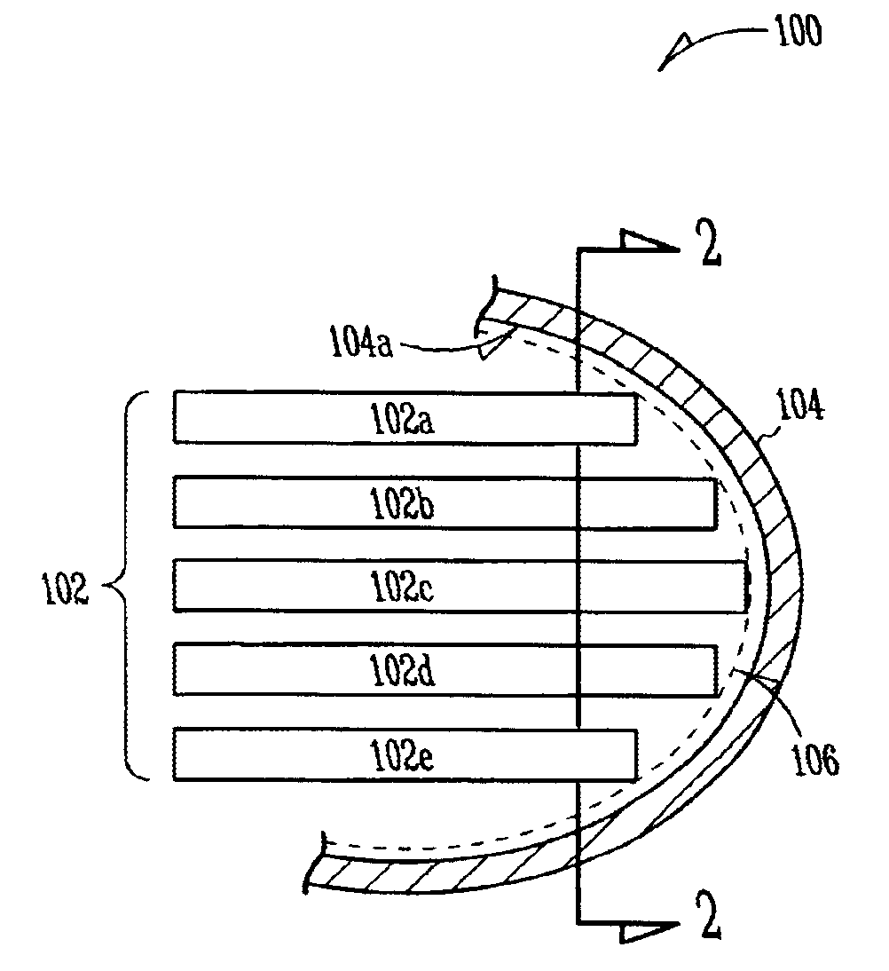
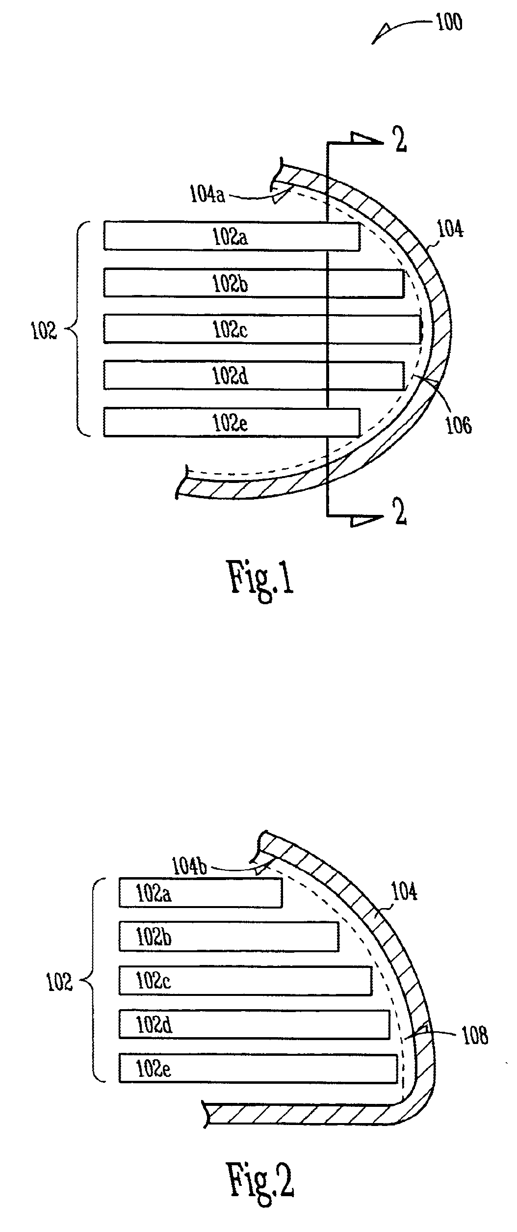
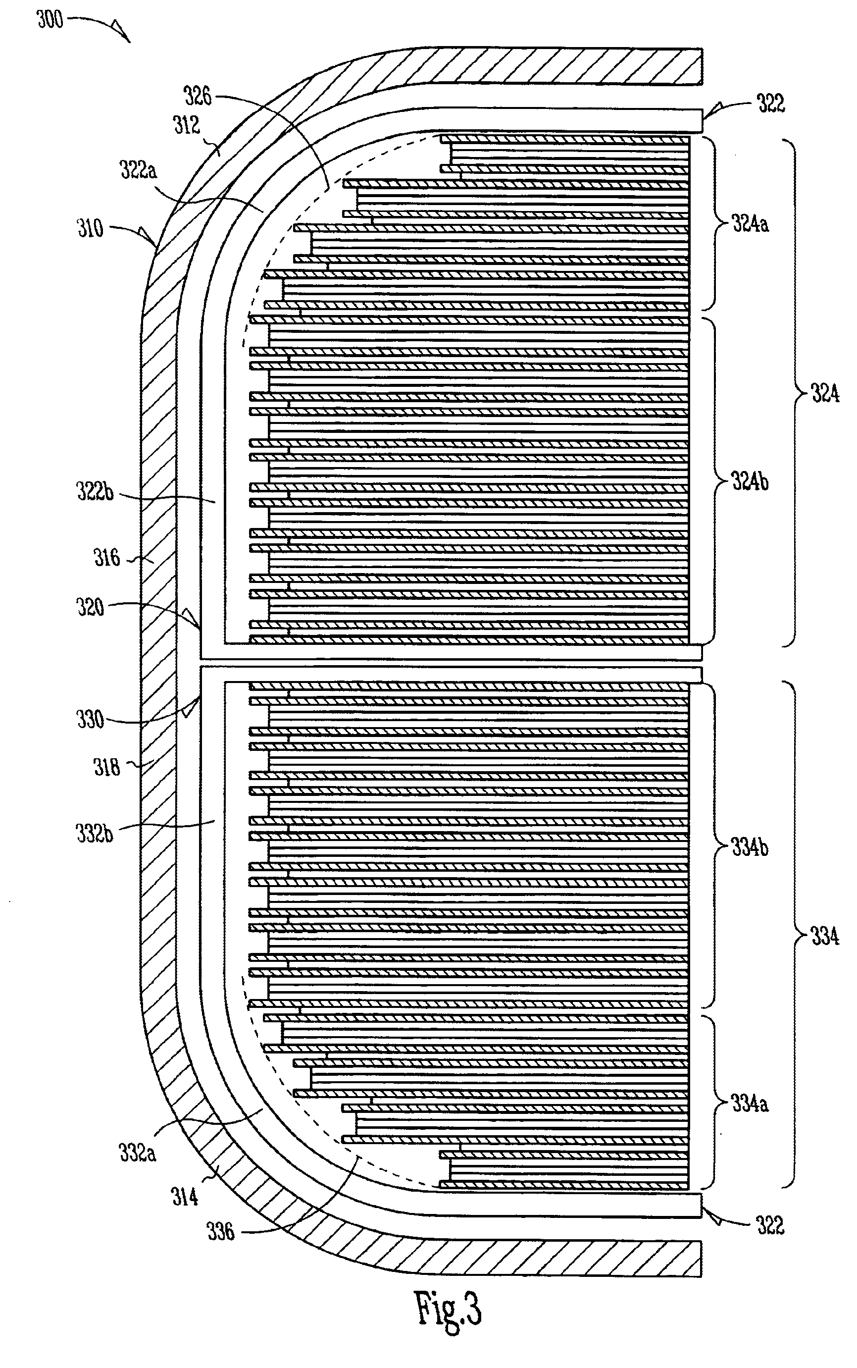
One problem with these types of flat capacitors and their stacked arrangement in implantable device housings is that the walls of the cases are incompatible with the rounded edges and corners of implantable device housings.
Juxtaposing these vertical walls and right-angle corners against the rounded interior portions of the housings inevitably leaves gaps or voids between the cases and housings.
These voids not only waste space, but ultimately force patients to endure implantable devices with larger housings than otherwise necessary.

Method used


Image

  • Implantable heart monitors having flat capacitors with curved profiles
  • Implantable heart monitors having flat capacitors with curved profiles
  • Implantable heart monitors having flat capacitors with curved profiles

Examples


Embodiment Construction

[0026]The following detailed description, which references and incorporates the above-identified figures, describes and illustrates one or more specific embodiments of the invention. These embodiments, offered not to limit but only to exemplify and teach, are shown and described in sufficient detail to enable those skilled in the art to implement or practice the invention. Thus, where appropriate to avoid obscuring the invention, the description may omit certain information known to those of skill in the art.

[0027]As used herein, the term “profile” refers to the general outline of a portion of an object taken in or projected onto a plane generally perpendicular to a major surface of the object. Thus, for example, in some flat capacitors, profile means the outline of the capacitor case and / or the capacitor stack taken in a plane perpendicular to the major surfaces of the case or the capacitor stack.

[0028]As used herein, the term “staggered” refers to the existence of an offset betwee...


PUM


Abstract

Implantable heart-monitoring devices, such as defibrillators, pacemakers, and cardioverters, detect onset of abnormal heart rhythms and automatically apply corrective electrical therapy, specifically one or more bursts of electric charge, to abnormally beating hearts. Critical parts in these devices include the capacitors that store and deliver the bursts of electric charge. Some devices use flat aluminum electrolytic capacitors have cases with right-angle corners which leave gaps when placed against the rounded interior surfaces of typical device housings. These gaps and voids not only waste space, but ultimately force patients to endure implantable devices with larger housings than otherwise necessary. Accordingly, the inventors devised several capacitor structures that have curved profiles conforming to the rounded interior surfaces of device housings. Some exemplary capacitor embodiments include two or more staggered capacitor elements, and other embodiments stagger capacitors of different types and / or sizes.

Description

CROSS-REFERENCE TO RELATED APPLICATIONS[0001]This application is a continuation of U.S. Application Ser. No. 10 / 287,285, filed on Nov. 4, 2002, now issued as U.S. Pat. No. 6,674,634, which is a division of U.S. Application Ser. No. 09 / 705,976, filed on Nov. 3, 2000, now issued as U.S. Pat. No. 6,522,525, the specifications of which are incorporated by reference herein.[0002]This application is related to U.S. Application Ser. No. 09 / 706,447, filed on Nov. 3, 2000, now issued as U.S. Pat No. 6,699,265, entitled FLAT CAPACITOR FOR AN IMPLANTABLE MEDICAL DEVICE, which is incorporated herein by reference in its entirety.TECHNICAL FIELD[0003]This invention relates generally to electrolytic capacitors and, more particularly to flat electrolytic capacitors for use in implantable heart monitors.BACKGROUND OF THE INVENTION[0004]Since the early 1980s, thousands of patients prone to irregular and sometimes life threatening heart rhythms have had miniature heart-monitoring devices, such as defi...

Claims


Application Information

Patent Timeline
Patent Type & Authority Patents(United States)
IPC IPC(8): H01G9/045H01G9/10A61N1/40A61N1/375A61N1/39H01G9/08
CPCH01G9/08A61N1/375A61N1/3968A61N1/37512A61N1/3758
Inventor O'PHELAN, MICHAEL J.SCHMIDT, BRIAN L.
Owner CARDIAC PACEMAKERS INC
Learn More