Downlink signal processing in CDMA systems utilizing arrays of antennae

Inactive Publication Date: 2006-01-10
INTEL CORP
View PDF174 Cites 161 Cited by
  • Summary
  • Abstract
  • Description
  • Claims
  • Application Information

AI Technical Summary

Benefits of technology

[0011]It is another object of the present invention to provide a method for determining the downlinking sign

Problems solved by technology

A significant fraction of the interference and noise experienced by each channel originates from the transmissions that are geographically localized such as transmissions from other users of the communication frequency.
Unfortunately, even in those cases in which mathematically orthogonal codes are utilized, the implementation of those codes on commercially feasible equipment a

Method used


Image

  • Downlink signal processing in CDMA systems utilizing arrays of antennae
  • Downlink signal processing in CDMA systems utilizing arrays of antennae
  • Downlink signal processing in CDMA systems utilizing arrays of antennae

Examples


Embodiment Construction

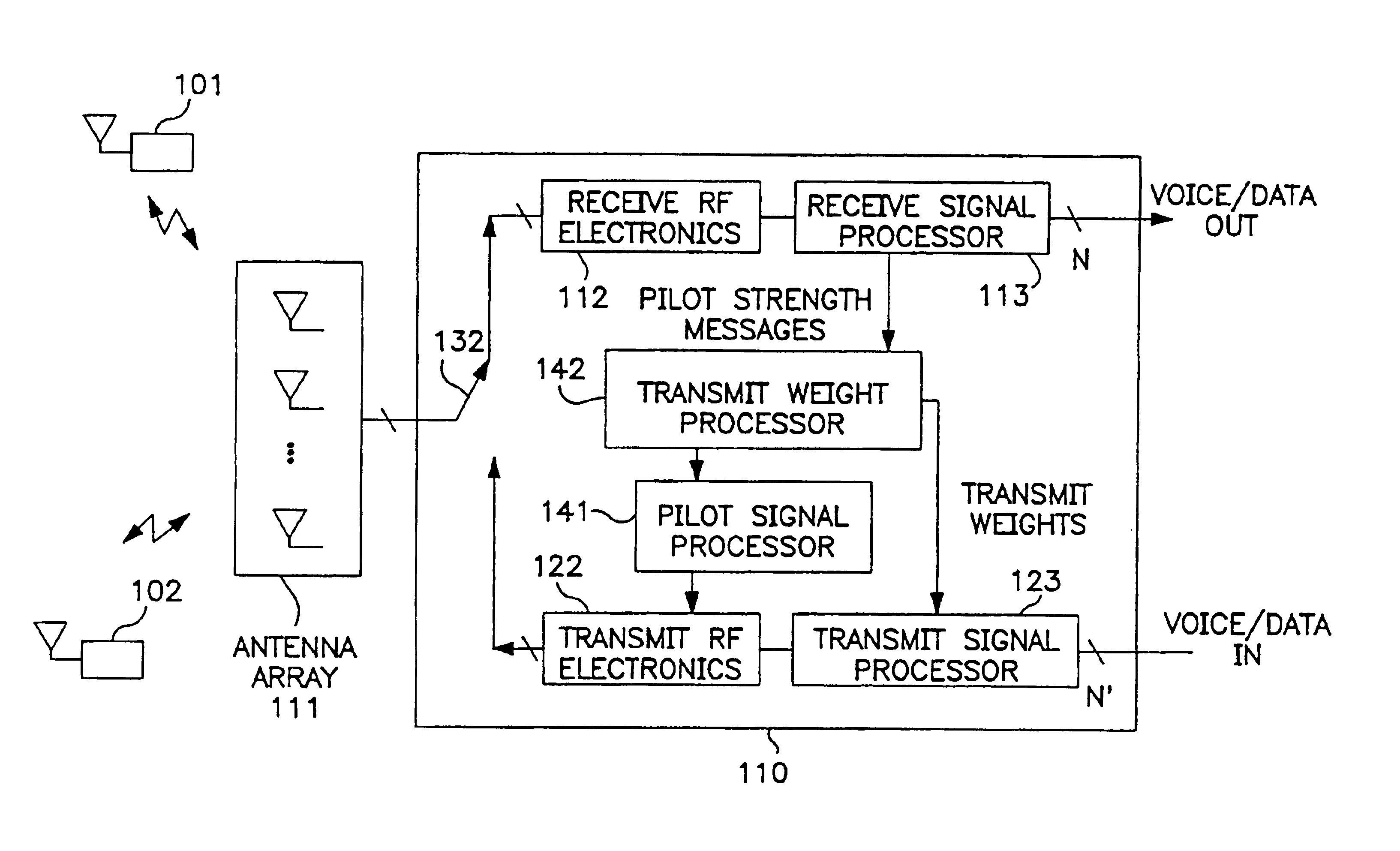
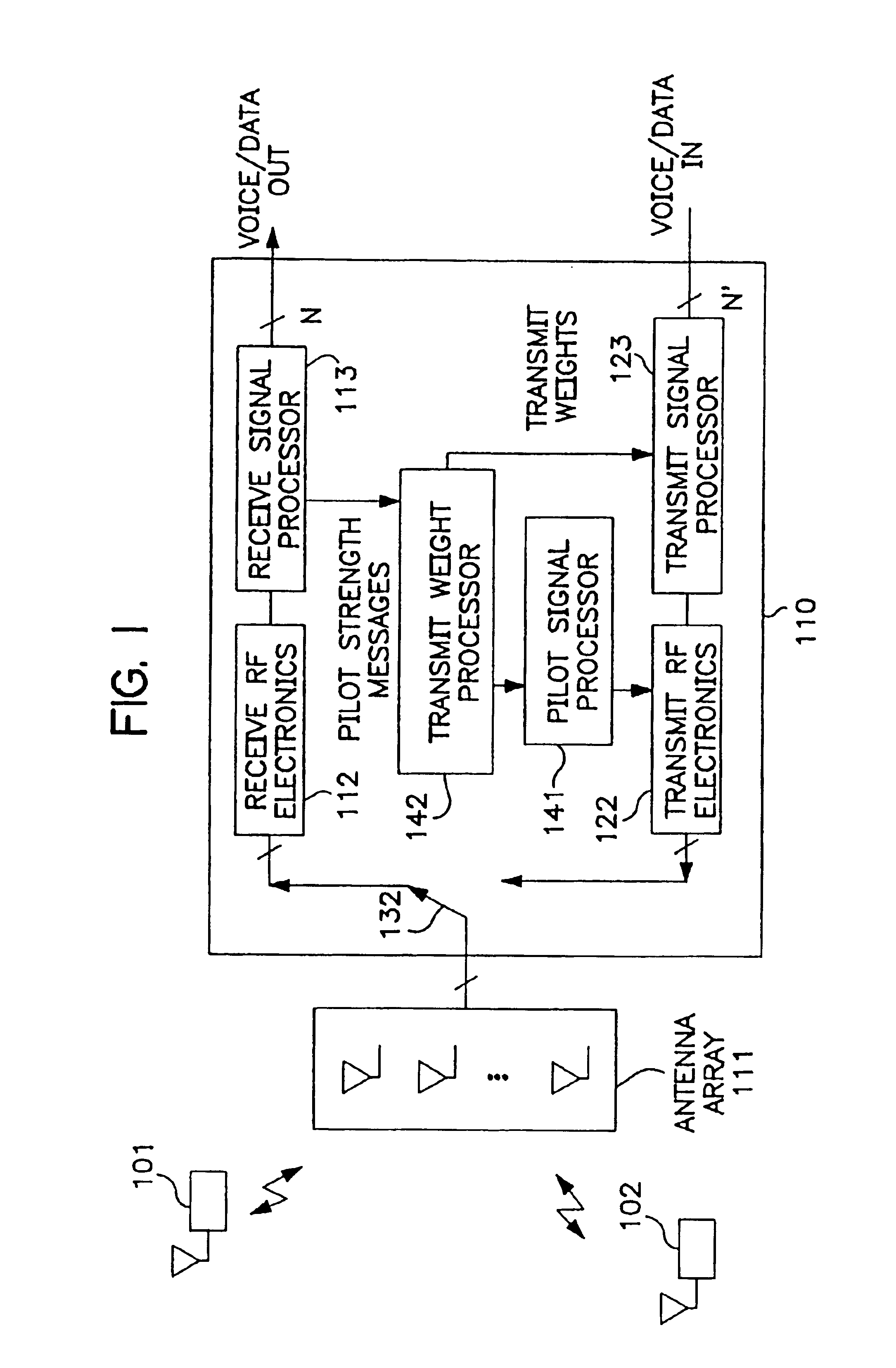
[0015]The manner in which the present invention obtains its advantages may be more easily understood with reference to FIG. 1. FIG. 1 is a block diagram of the signal-processing portion 110 of a BS employing an antennae array 111 to communicate with a number of cellular users. Exemplary users are shown at 101 and 102. The signals from the antennae are coupled to RF receiving circuit 112. A “Switch”132 determines whether the antennae are connected to receiving circuit 112 or transmitting circuit 112. RF receiving circuit 112 down converts the RF signal from each antenna in array 111 from the uplink RF frequency and digitizes the base-band signal to provide an in phase and quadrature signal to receive signal processor 113 for each antenna and stores those values in memory. The in phase signal digitized at time t for the ith antenna is denoted by Ii(t), and the quadrature signal by Qi(t) in the following discussion. The base-band signal is typically over sampled to assure that the erro...


PUM


Abstract

The present invention is a method for operating a base station (BS) for transmitting information to a subscriber unit (SU) in a cellular communication system. The information is included in a downlink signal sent from a signal processing circuit through an array of antennae. The processing depends on a weight set that is utilized in generating individual signals to be sent on individual antennae in the array to the SU. The weight set is determined by transmitting a plurality of pilot downlink signals from BS to the SU, each pilot downlink signal being processed with a different weight set than that used to process the other pilot downlink signals. Report signals are received for each of the pilot downlink signals and are compared to determine which weight set should be utilized. The present invention may be practiced within existing CDMA cellular standards such as the IS-95 standard.

Description

FIELD OF THE INVENTION[0001]This invention relates to the field of wireless communication systems, and more specifically, to a method for determining the proper communication parameters to be utilized by a communication station that uses a multiple element antenna array to reduce noise and interference in CDMA-based digital cellular and similar systems.BACKGROUND OF THE INVENTION[0002]The success of cellular telephone systems has led to increased demand. To provide the communication bandwidth needed to satisfy this increased demand, technologies have been developed that enable several conversations to occur simultaneously in a single frequency band. In time division multiple access (TDMA), each communication frequency is divided into “time slots”, each time slot being used for a separate conversation. A second technique relies on code division multiple access (CDMA) to increase the number of users that can share any given communication frequency. In such systems each user encodes hi...

Claims


Application Information

Patent Timeline
IPC IPC(8): H04B7/216H04Q7/00H04B7/06H04B7/08H04B7/26
CPCH04B7/0647
Inventor YUN, LOUIS C.TROTT, MITCHELL D.
Owner INTEL CORP
Why Eureka
Try Eureka