Communication system, communication terminal and communication method

a technology of communication terminal and communication system, applied in the field of communication system, can solve the problems of inability to establish wired communication, risk of disconnection, and inability to appropriately switch between wireless communication and wired communication, so as to achieve effective utilization of wireless communication resources, avoid congestion by excessive wireless communication, and avoid congestion

Active Publication Date: 2006-01-10
SONY CORP
View PDF23 Cites 167 Cited by
  • Summary
  • Abstract
  • Description
  • Claims
  • Application Information

AI Technical Summary

Benefits of technology

[0053]In addition, according to an embodiment of the communication system of the present invention, when the communication terminal is connected to the electric power supplying means or the like while communications via the wireless communication system are being performed, whether or not the communication partner is also capable of using the wired communication system via the electric power line may be determined. Then, if the wired communication system is available on both sides, the communication terminal may negotiate with the communication partner, automatically switch the communication system from the wireless communication system to the carrier communication of the wired communication system via the electric power line, and continue communicating. Thus, wireless communication resources may be utilized effectively while avoiding congestion by excessive wireless communications.
[0054]In addition, according to an embodiment of the communication system of the present invention, even in a case where electric power line carrier communication cannot be performed directly with the communication partner currently in wireless communication, by selecting an electric power line carrier gateway according to a predefined routing rule, communication may be continued via carrier communication using the selected electric power line. As such, communication may be performed by switching between the wireless communication system and the wired communication system via the optimum electric power line as deemed appropriate, while monitoring the availability of the respective communication systems. Thus, even in systems, such as a wireless LAN and the like, lacking in wireless communication resources, the wireless communication resources thereof may be utilized effectively. In addition, by communicating via the electric power line while charging the communication terminal, since the charging power for the secondary battery is not used for wireless communications, electric power resources of the secondary battery may be utilized effectively. Accordingly, the power to charge the secondary battery may be used efficiently for charging. Further, in communicating via the electric power line, since there is no need to expand the communication network, communication medium costs, such as a communication cables and the like, may be reduced as compared to normal wired communication.
[0055]In addition, in an embodiment of the communication system according to the present invention, when a communication failure occurs in the wireless communication system due to interference from another communication system, the communication terminal may switch from the wireless communication system to the wired communication system via the electric power line by connecting itself to the electric power supplying means. Particularly, the communication terminal may switch from the wireless communication system to the wired communication system by connecting itself to the electric power supplying means within a prede

Problems solved by technology

However, in the electric power line carrier system mentioned above in which the wireless line and the electric power line are used concomitantly, despite the versatility of being able to plug it in any socket, no consideration is given to appropriately switching between wireless communication and wired communication.
In other words, regardless of whether the cradle (the battery charger) is plugged in or not, if the cordless handset is mounted on the cradle (the battery charger), an operation of switching from wireless to wired communication takes place, and thus, situations in which wired communication cannot be established may arise.
In

Method used


Image

  • Communication system, communication terminal and communication method
  • Communication system, communication terminal and communication method
  • Communication system, communication terminal and communication method

Examples


first embodiment

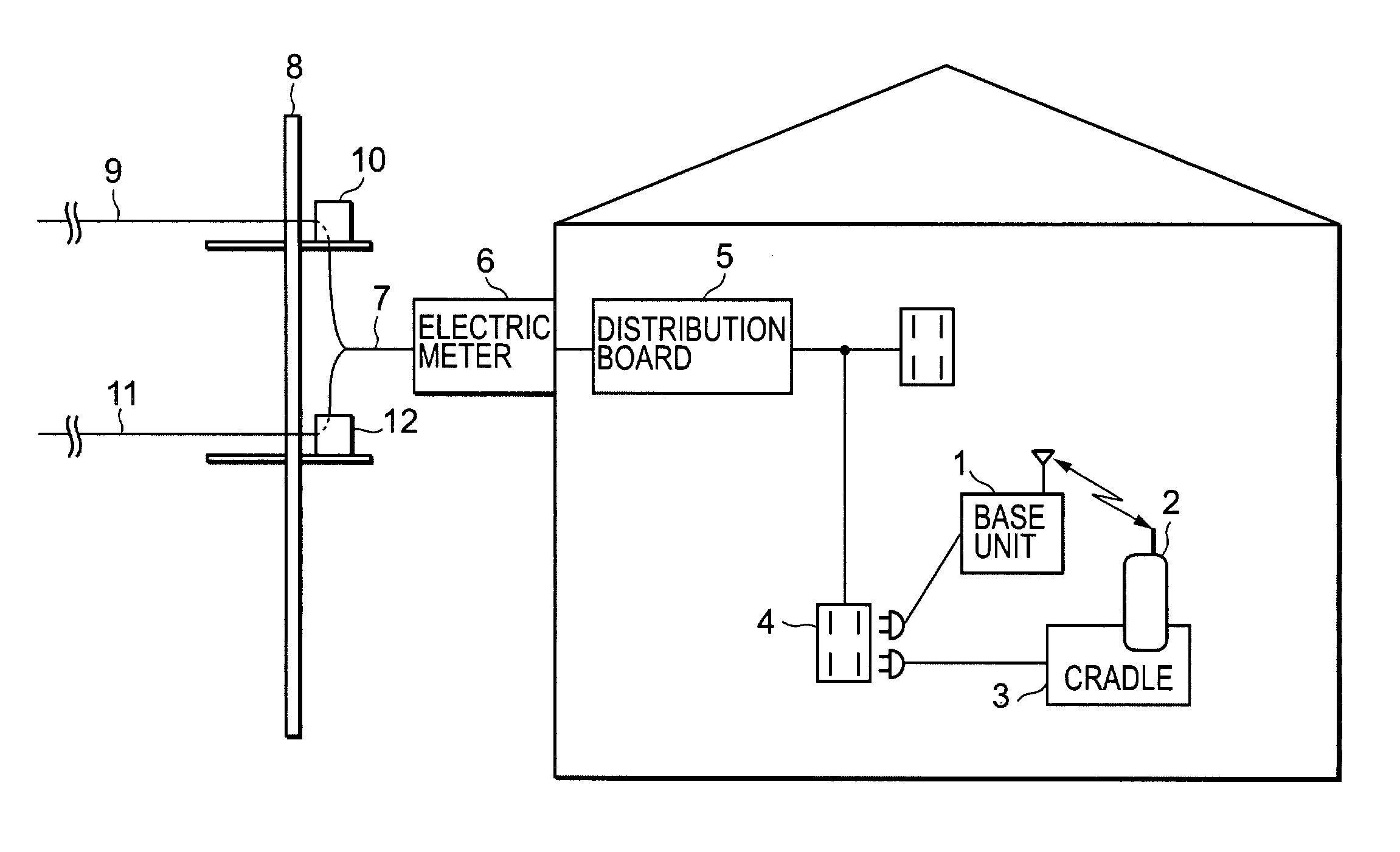
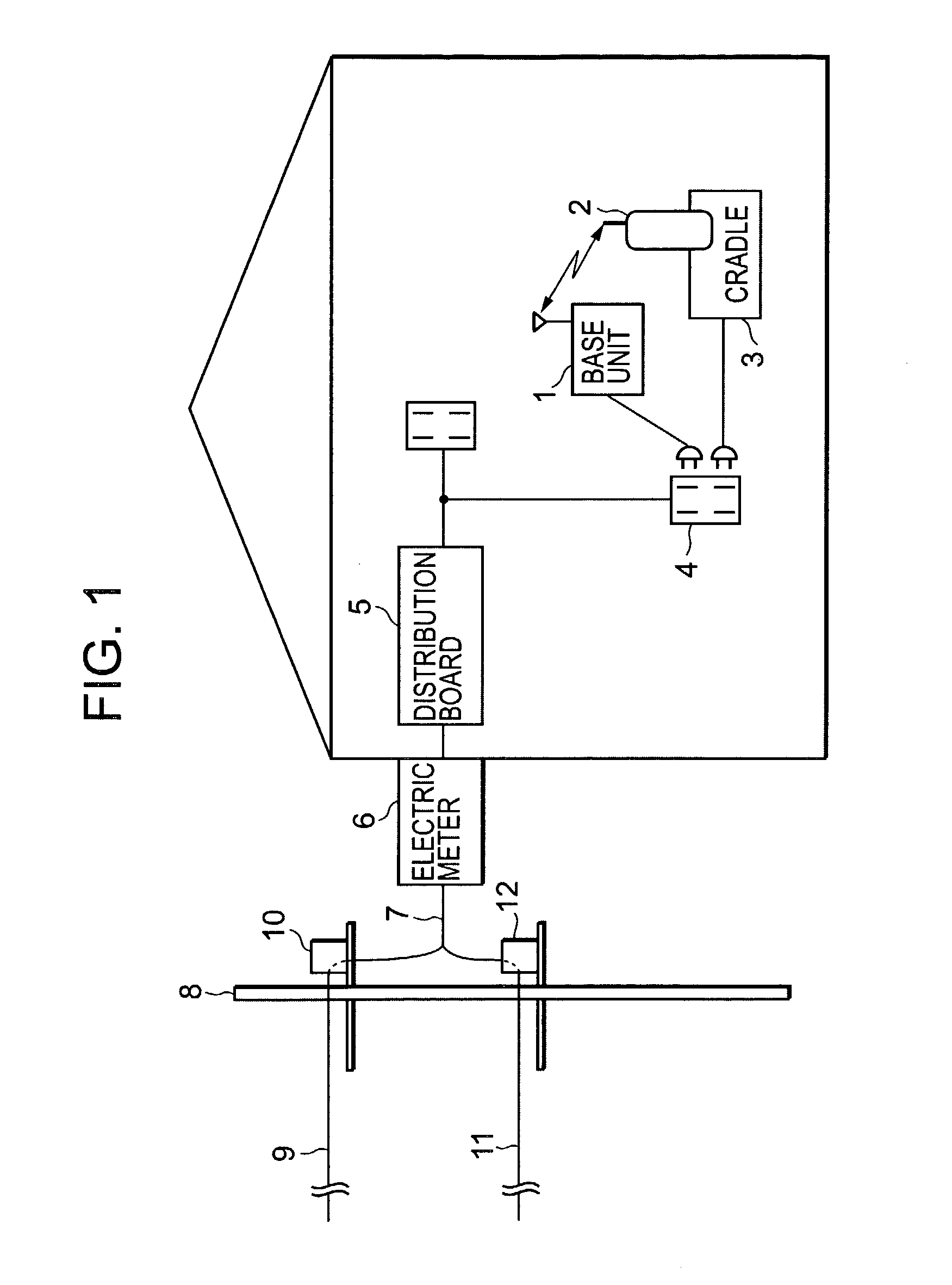
[0084]FIG. 1 is a conceptual diagram of a communication system for switching between wireless communication and wired communication using a base unit and a cordless handset according to a first embodiment of the present invention. In other words, this drawing illustrates a concept of a communication system in which a cordless handset 2 is switched between wireless communication and wired communication. In this drawing, the communication system includes a base unit 1, the cordless handset 2 which communicates via the base unit 1, a cradle (battery charger) 3 for charging the cordless handset 2, a socket 4 for connecting each of the base unit 1 and the cradle 3 to an electric power line, a distribution board 5 for distributing the electric power line, an electric meter 6 for measuring the integral electric power in the facility, a lead-in wire 7 for leading the electric power line in from outside, a pole-top potential transformer 10 mounted on an electric pole 8 for stepping a high vo...

second embodiment

[0097]FIG. 3 is a conceptual diagram of a communication system for switching between wireless communication and wired communication using a personal computer with a built-in battery charging function according to a second embodiment of the present invention. In other words, this drawing illustrates a concept of a communication system for switching a portable terminal equipped with a battery charging function, namely, a personal computer 51, between wireless communication and wired communication. The personal computer 51 has a wireless card 52 for performing wireless communication and an adapter 53 for charging. Accordingly, a cradle such as that described in the first embodiment is not present, and charging may be performed as required through the adapter 53. Since the wiring system beyond a socket 55 is the same as that in FIG. 2 described above, descriptions thereof are omitted.

[0098]When the personal computer 51 is in a normal in-use condition, wireless communication is performed...

third embodiment

[0126]A communication system according to a third embodiment relates to a communication system which is provided with both a wireless LAN communication system and an electric power line carrier communication system, and which switches between these communication modes in accordance with communication conditions (hereinafter, referred to as communication quality levels). In addition, the term communication mode refers to the respective communication systems and their transmission rates in combination. Since it is generally unlikely that stable communication conditions may be secured for both the wireless LAN and electric power line carrier communication at the same time, when the communication quality level of either communication system becomes low, communication is performed by switching to the communication mode of the communication system having the higher communication quality level. In this case, the communication quality level which is taken as a criterion for judging whether ...


PUM


Abstract

From an electric pole outside to a cordless handset inside a building/facility, a communication line is established via an electric power line. At this point, it is judged whether or not electric power line communication is possible, and if electric power line communication is possible, the communication line between the cordless handset and a base unit is switched to an electric power line communication system, and a communication line is formed via an optical fiber cable from the electric power line. By measuring the communication quality levels of all lines of the wireless and electric power lines, the communication line having the highest communication quality level may be selected.

Description

CROSS REFERENCE TO RELATED APPLICATIONS[0001]The present document claims priority to Japanese Priority Document JP 2001-360412, filed in the Japanese Patent Office on Nov. 27, 2001, as well as Japanese Priority Document JP 2002-148227, filed in the Japanese Patent Office on May 22, 2002, the entire contents of which are incorporated herein by reference to the extent permitted by law.BACKGROUND OF THE INVENTION[0002]1. Field of the Invention[0003]The present invention relates to a communication system capable of wireless or wired communications, and particularly to a communication system capable of switching between a wireless line and an electric power line as deemed appropriate in performing communications. In addition, the present invention relates to a communication system capable of switching between communication modes having different transmission rates in performing communications via the wireless line or the electric power line.[0004]2. Description of the Related Art[0005]In...

Claims


Application Information

Patent Timeline
IPC IPC(8): H04M9/00H04B1/74H04B3/54H04L1/00H04L1/16H04L1/20H04L1/22H04L12/28H04M1/00H04M1/725H04W84/12H04W88/06
CPCH04B3/54H04L1/0002H04L1/0017H04L1/203H04L1/22H04L12/5692H04M1/725H04B2203/5441H04B2203/5445H04B2203/5495H04W24/00H04W40/00H04W76/02H04L1/16H04W76/10
Inventor AKIYAMA, KEIJIKONYA, SATOSHI
Owner SONY CORP
Why Eureka
Try Eureka