Interactive weather advisory system

a technology of weather advisory system and weather information, applied in the field of interactive weather advisory system, can solve the problems of insufficient specific identification and adequate warning of personal risks, interpretation errors, and insufficient reporting system of existing weather information system

Inactive Publication Date: 2006-01-10
LOCATOR IP
View PDF32 Cites 74 Cited by
  • Summary
  • Abstract
  • Description
  • Claims
  • Application Information

AI Technical Summary

Benefits of technology

[0014]The communication network transmits each individualized weather output signal to the particular communicator device defined in the user profile included in the user-defined parameter corresponding with the real-time weather data and prediction of events. Thus, a user can receive weather information in real-time specific to the user's immediate spatial location regardless of whether or not the user's location remains fixed or dynamic throughout time.

Problems solved by technology

Requests for detailed weather information for specific applications outnumber the governments' ability to process them.
Often, this interpretation is made erroneously.
Even worse, these products are usually regional or national in scope, and may not apply to a particular location where various local activities are underway.
Essentially, the existing reporting system is insufficient to specifically identify and adequately warn of personal risk.
Furthermore, if the threat is imminent, the existing system cannot and does not provide preventive measures for each user near or at the threat.
Thus, by default, distant or unaffected users are placed “on alert” unnecessarily when the threat may be moving away from their location.
Unknown to the family at midday, some clusters of showers are intensifying, and will place dangerous lightning over the game field.
While the morning weather report was not completely inaccurate, the participants and spectators are exposed to risk.
They also failed to link their limited knowledge of the weather to their own needs and risk exposure.
Clearly, these people were forced to interpret outdated, limited information, as applied to their specific application.

Method used


Image

  • Interactive weather advisory system
  • Interactive weather advisory system
  • Interactive weather advisory system

Examples


Embodiment Construction

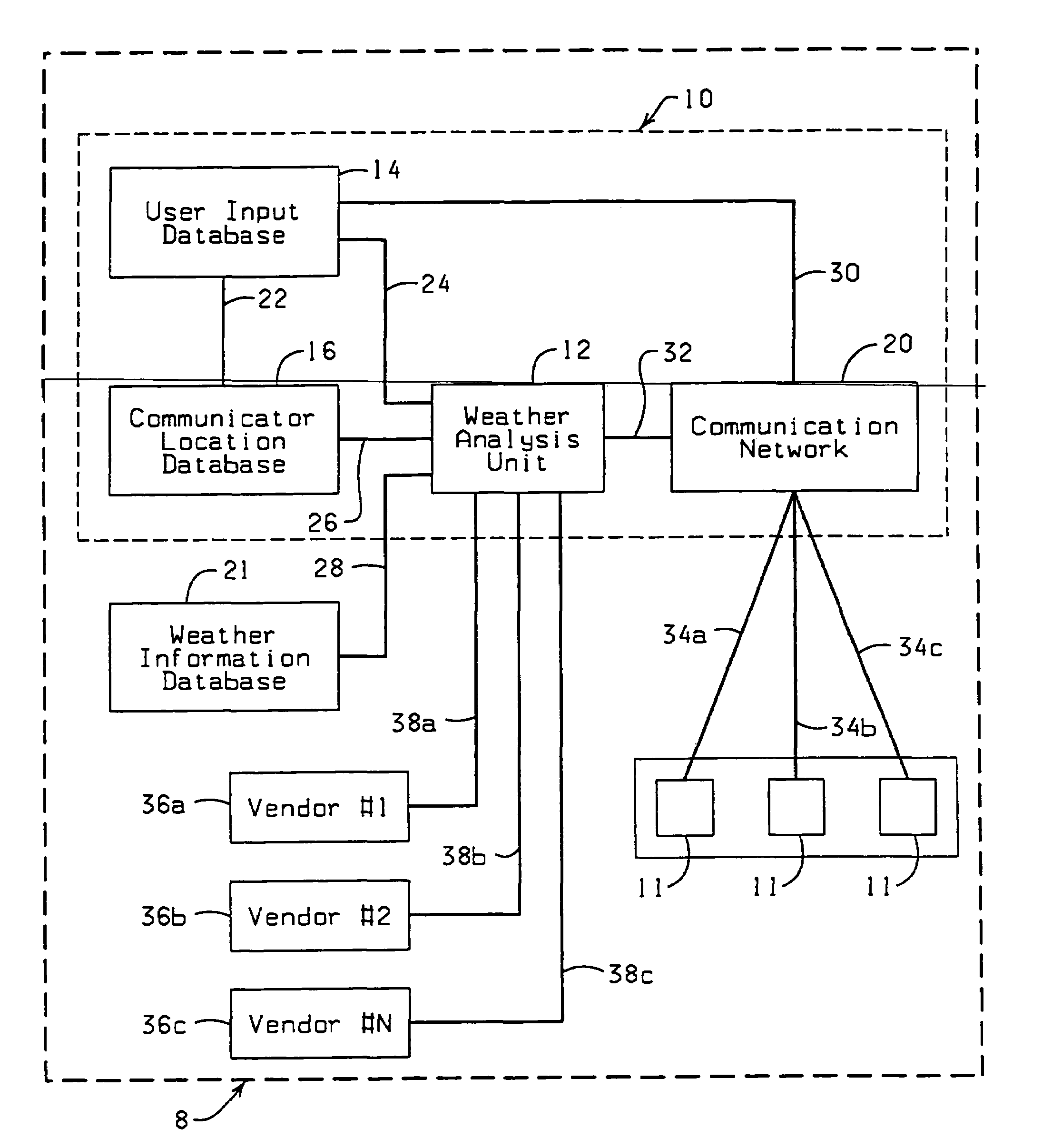
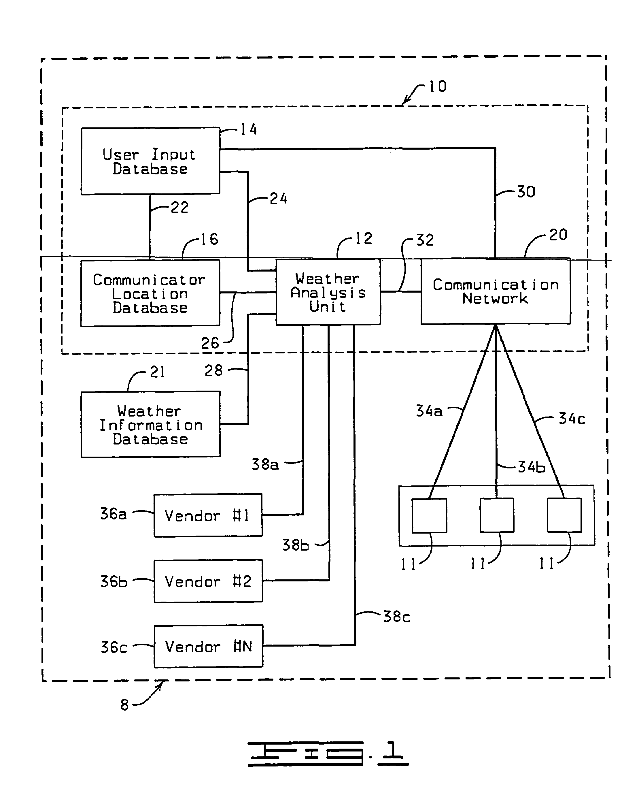
[0018]Referring now to the drawings and more particularly to FIG. 1 shown therein in block diagram form, is an interactive weather advisory system 8, constructed in accordance with the present invention. The weather advisory system 8 is provided with a broadcast network 10 for selectively transmitting individualized weather output signals to remote communicator devices 11. The broadcast network 10 includes a weather analysis unit 12, a user input database 14, a communicator location database 16, and a communication network 20. The weather analysis unit 12 receives real-time weather data from a weather information database 21. The weather information database 21 can be located at the broadcast network 10, or remotely from the broadcast network 10.

[0019]The weather analysis unit 12, the user input database 14, the communicator location database 16, the weather information database 21, and the communication network 20, interrelate and communicate via signal paths 22, 24, 26, 28, 30 and...


PUM


Abstract

A broadcast network for selectively transmitting individualized weather forecast signals to remote communicator devices. The broadcast network comprising a user input database, a communicator location database, a weather analysis unit and a communication network. The user input database contains user-defined parameters, each of the user-defined parameters includes a user profile. The user profile utilizes a user identifier code and identifies a communicator device associated with a particular user. The communicator location database contains data indicative of the real-time spatial locations of the communicator devices. The weather analysis unit compares the spatial location of each communicator device contained in the communicator location database with real-time weather forecast data or weather data and generates an individualized weather forecast signal upon demand of a user. The communication network receives the individualized weather output signals and transmits the individualized weather output signals to the communicator devices identified by the user identifier codes.

Description

CROSS-REFERENCE TO RELATED APPLICATIONS[0001]The present patent application is a continuation of U.S. Ser. No. 10 / 355,971, filed on Jan. 31, 2003, now U.S. Pat. No. 6,836,730 which is a continuation-in-part of U.S. Ser. No. 10 / 322,187, filed on Dec. 16, 2002, now U.S. Pat. No. 6,754,585, which is a continuation of U.S. Ser. No. 09 / 624,668, filed on Jul. 24, 2000, now U.S. Pat. No. 6,505,123. The entire content of each of the above-referenced patent applications is hereby incorporated herein by reference.STATEMENT REGARDING FEDERALLY SPONSORED RESEARCH OR DEVELOPMENT[0002]Not applicable.BACKGROUND OF THE INVENTION[0003]During recent years, the demand for detailed weather information has risen sharply. Personal computers and communication devices have increased the demand for more information because of their power to gather, manipulate, transmit and receive data. As a result, specialized information and value-added services are in great demand. End users no longer desire to gather, m...

Claims


Application Information

Patent Timeline
Patent Type & Authority Patents(United States)
IPC IPC(8): G01W1/00G01W1/10G06F17/30H04LH04L12/18H04L29/08
CPCH04L69/329G01W1/10G06F17/3087H04L12/1859H04W4/02H04W4/021H04W4/023H04W4/18H04W4/20H04L67/20H04L67/306H04L67/04H04L67/18G01W1/00G01K2203/00H04L67/26H04L67/53G06F16/9537H04L67/52H04L67/55H04N21/258H04W4/029Y02A90/10
Inventor ROOT, STEVEN A.ROOT, MICHAEL R.
Owner LOCATOR IP
Why Eureka
Try Eureka