Apparatus and method for opening and closing stacked hydroforming dies

Inactive Publication Date: 2006-01-17
METALSA SA DE CV
View PDF15 Cites 50 Cited by
  • Summary
  • Abstract
  • Description
  • Claims
  • Application Information

AI Technical Summary

Benefits of technology

[0010]In this way, the hydroforming apparatus performs two or more hydroforming operations concurrently to decrease process time and increase productivity without increasing press tonnage. The ram assists an operator to open both the dies that are adjacent the ram and other dies distant from the ram. Guide pins transmit certain portions of ram displacement to dies distant from the ram to assist in opening those dies. Linear actuators are used in coordination with the ram to assist in opening die cavities near the ram, and to move interior dies that cannot be opened directly by the ram. This feature reduces process time and further increases the production rate.

Problems solved by technology

Although the die cavity is usually somewhat larger than the workpiece to be hydroformed, movement of the two die sections from the opened position to the closed position may, in some instances, cause some mechanical deformation of the workpiece.
Use of a single hydroforming die within a single hydroforming apparatus has been found to be somewhat inefficient from a time consumption standpoint.
These filling and emptying steps can consume relatively long periods of time, particularly when the articles to be formed are physically large, as is often the case in the manufacture of vehicle frame components.
This inefficiency is amplified when the hydroforming apparatus is used to manufacture products in relatively high volumes, as is also the case in the manufacture of vehicle frame components.
Although a ram can assist an operator to open one die cavity, other die cavities not in direct contact with the ram cannot be opened by the ram.
This deficiency increases process time and slows the production rate.

Method used


Image

  • Apparatus and method for opening and closing stacked hydroforming dies
  • Apparatus and method for opening and closing stacked hydroforming dies
  • Apparatus and method for opening and closing stacked hydroforming dies

Examples


Embodiment Construction

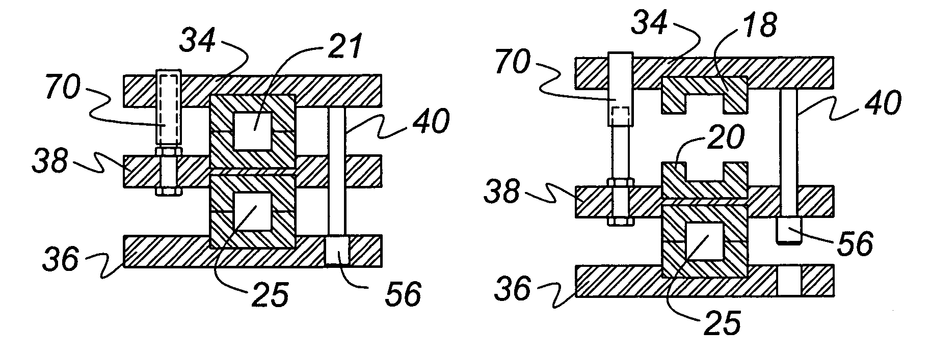
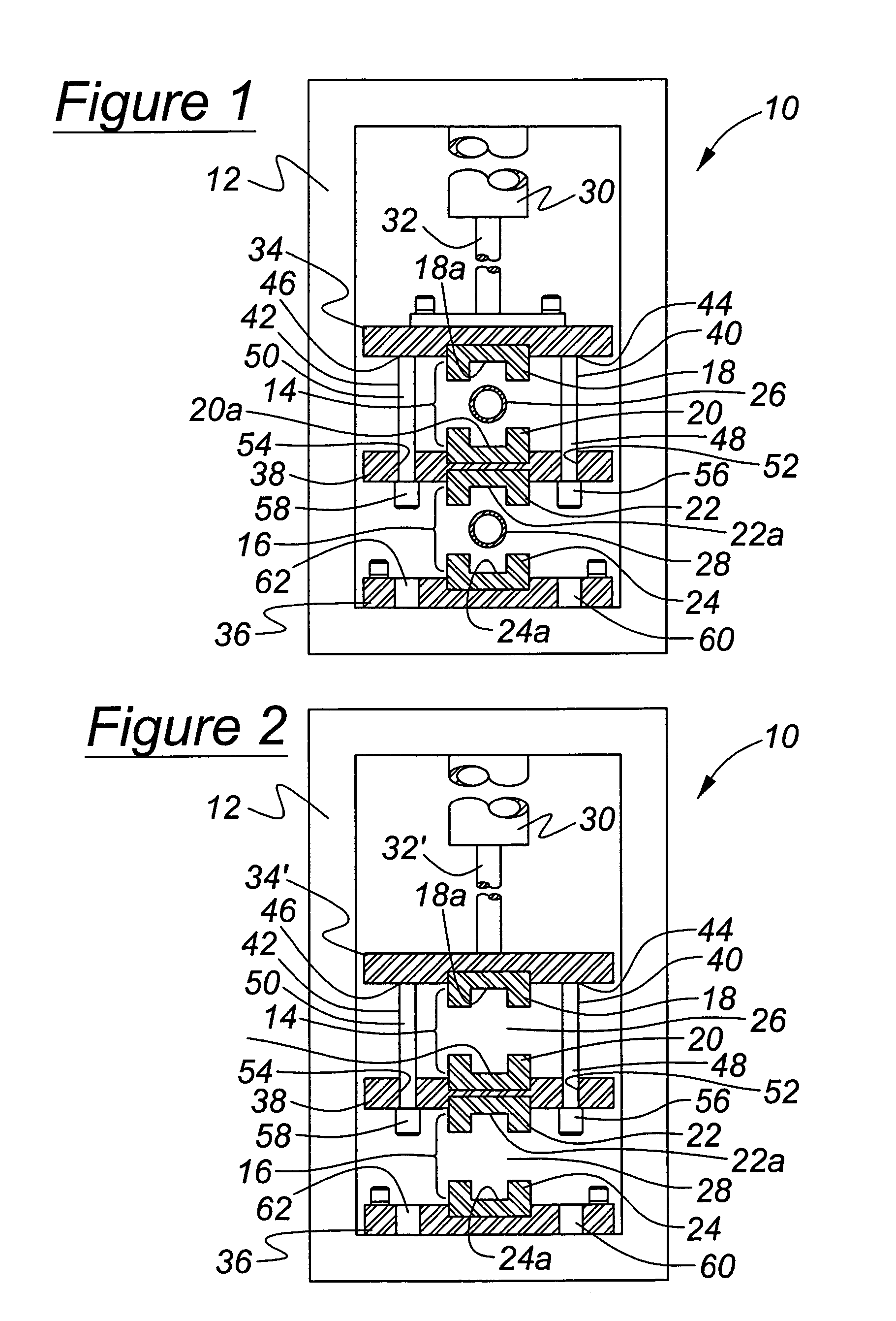
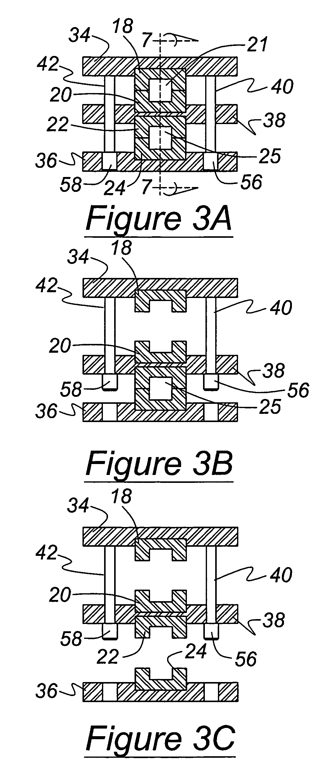
[0019]Referring now to the drawings, there is illustrated in FIG. 1 an apparatus, indicated generally at 10, for performing a hydroforming process in accordance with this invention. The apparatus 10 includes a frame 12 that is sized to support hydroforming dies arranged in a vertically oriented relationship, two of which are indicated generally at 14, 16. Although this invention will be described and illustrated in the context of the two vertically stacked hydroforming dies 14 and 16, it will be appreciated that this invention can be practiced with a greater number of such hydroforming dies if desired. Furthermore, the hydroforming dies can be arranged within the hydroforming apparatus 10 in any desired direction other than the illustrated vertical direction. For example, the dies may be stacked horizontally, in which case the lateral plane of the dies is vertical, and the direction of their movement is horizontal.

[0020]The first die 14 includes a first pair of cooperating die secti...


PUM


Abstract

A hydroforming apparatus for concurrently performing two or more hydroforming operations includes a frame that is sized to support hydroforming dies in a stacked relationship. Each of the dies includes a pair of cooperating die sections having respective recesses that define a die cavity. Guide pins and actuating cylinders, attached to platens on which the die section are supported, move in coordination with a ram and assist in moving die sections that are distant from the ram. When the die cavities are opened, hollow tubular blanks are inserted between the spaced apart die sections of the first and second die. Next, the ram and the support mechanism move such that the pairs of cooperating die sections of the first and second dies engage one another. End feed cylinders are then moved laterally into engagement with the end the tubular blanks to facilitate the filling thereof with a hydroforming fluid. The pressure of the fluid within the tubular blanks is then increased to expand such a magnitude that the tubular blanks are expanded outwardly into conformance with the respective die cavities. Thus, the hydroforming apparatus is capable of performing two or more hydroforming operations concurrently to decrease the overall amount of operation cycle time and to increase overall productivity.

Description

BACKGROUND OF THE INVENTION[0001]This invention relates to hydroforming operations. More particularly the invention relates to coordinated movement of dies used to perform concurrently two or more hydroforming operations in a press.[0002]Hydroforming is a well known metal working process that uses pressurized fluid to expand a closed channel or tubular workpiece outwardly into conformance with the surface of a die cavity. A typical hydroforming apparatus includes a frame having two die sections supported for relative movement between opened and closed positions. The die sections have cooperating recesses, which together define a die cavity having a shape corresponding to a desired final shape for the workpiece. When moved to the open position, the die sections are spaced apart from one another to allow a workpiece to be inserted and removed from the die cavity. When moved to the closed position, the die sections are adjacent one another and enclose the workpiece within the die cavit...

Claims


Application Information

Patent Timeline
IPC IPC(8): B21D26/02
CPCB21D26/039Y10T29/49805B21D35/003
Inventor RAGER, CHRISTOPHER A.
Owner METALSA SA DE CV
Why Eureka
Try Eureka