Oxygen flow regulator

a flow regulator and oxygen technology, applied in the direction of valve operating means/release devices, process and machine control, instruments, etc., can solve the problems of additional cosmetic problems, c-clips do not offer adequate stability, and are separate from the regulators, so as to improve durability and stability

Inactive Publication Date: 2006-01-17
INOVO
View PDF30 Cites 17 Cited by
  • Summary
  • Abstract
  • Description
  • Claims
  • Application Information

AI Technical Summary

Benefits of technology

[0006]This combination of parts yields a one-piece regulator with improved durability and stability. In addition, the flow control knob is connected to the flow control body in such a way that the knob cannot separate from the regulator during use.
[0007]The modular system also permits the use of internal components which are fabricated from a different material than the yoke body. As such, the yoke body can be made from aluminum and the internal components can be made from brass. The resulting regulator can thus realize the advantageous of each material.

Problems solved by technology

In these devices, the c-clips do not offer adequate stability.
In addition, the flow control knob is usually snapped into place and can, therefore, accidentally separate from the regulator.
The use of two pieces also results in additional cosmetic problems.
For example, it can be difficult to uniformly color the two housings due to variations in anodizing the pieces.

Method used


Image

  • Oxygen flow regulator
  • Oxygen flow regulator
  • Oxygen flow regulator

Examples


Embodiment Construction

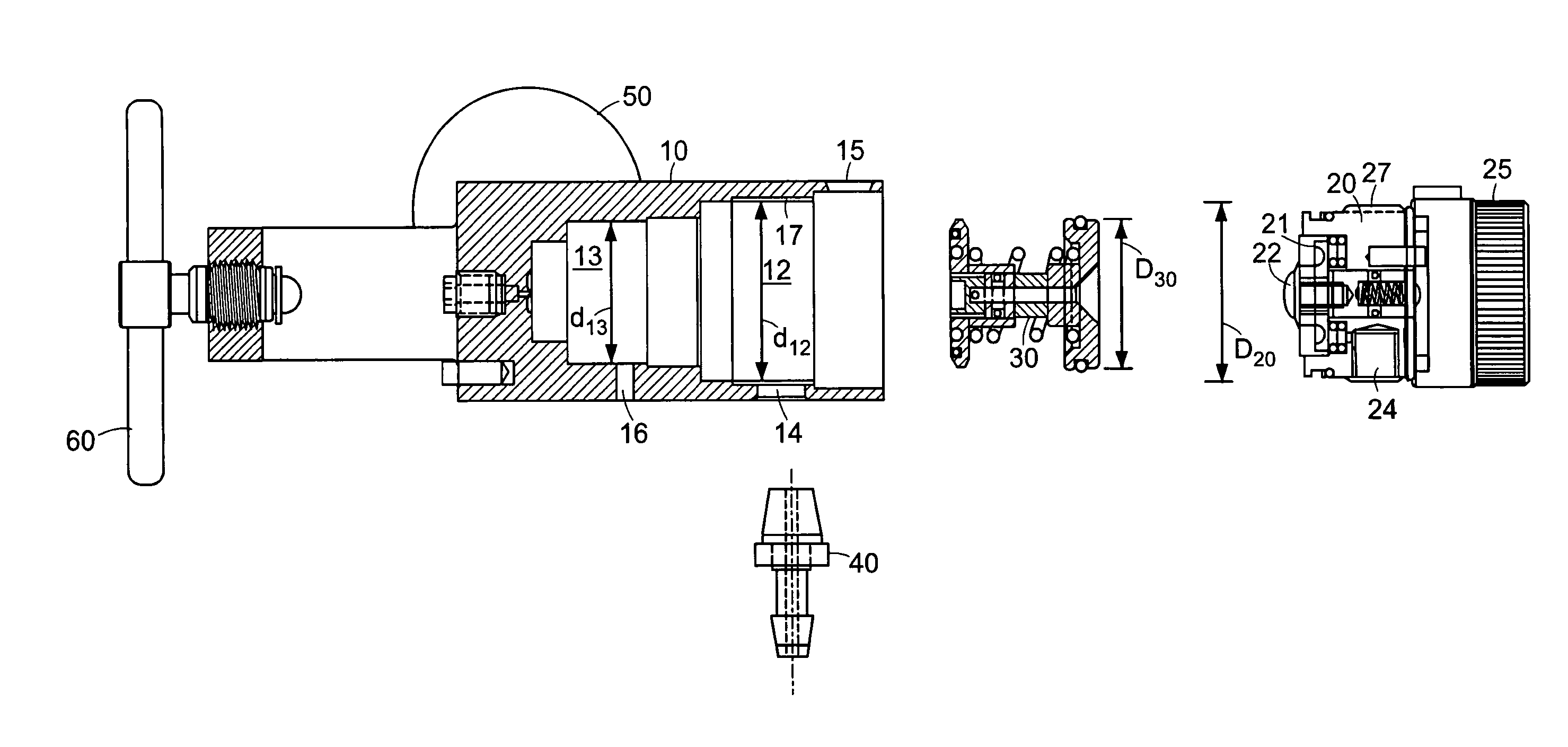
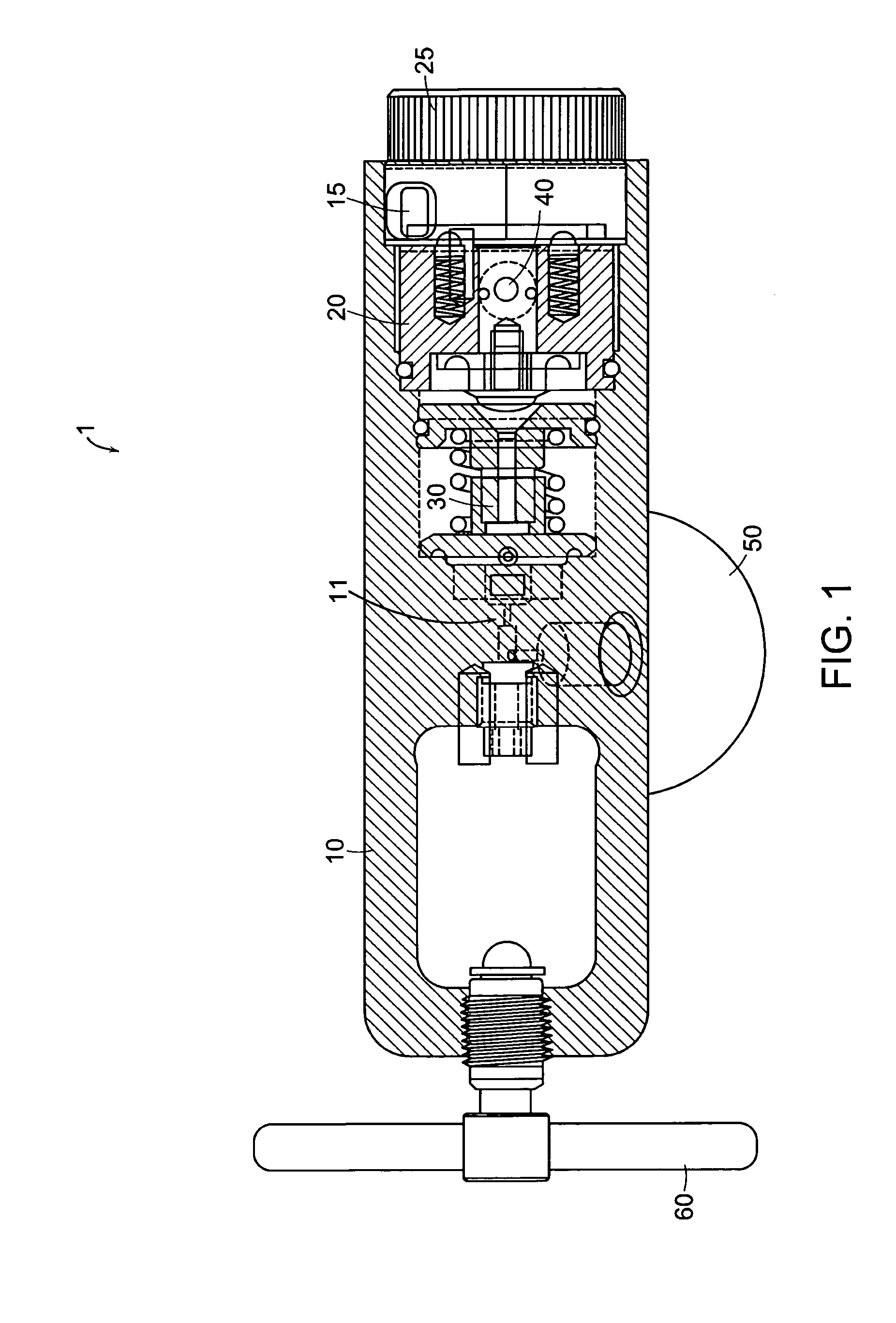
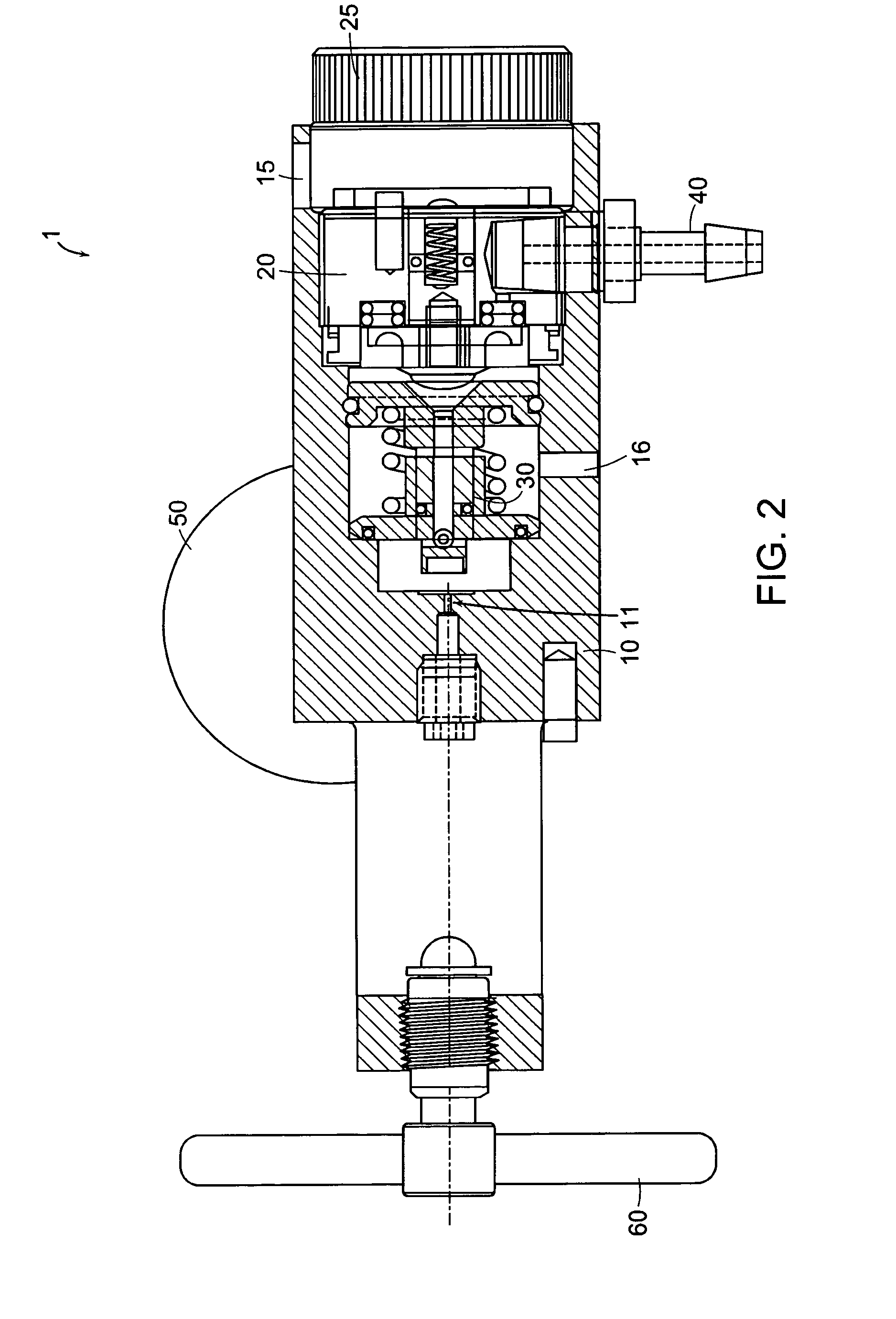
[0030]FIGS. 1 and 2 are cross-sectional drawings of a particular gas flow regulator. The regulator 1 includes a yoke body or housing 10, a flowmeter assembly element 20, a piston element 30 a fitting such as, a hose barb 40, a gauge 50 and a T-handle 60. The yoke body 10 is of a unibody construction to facilitate a secure and stable attachment to a gas supply cylinder (not shown). At a proximal end, the regulator is clamped to a cylinder or tank post of the supply cylinder by the handle 60. A pressure reducing region 11 of the yoke body 10 reduces the supply tank pressure to about 50 psi, as known in the art.

[0031]The piston 30 and flowmeter assembly 20 cooperate to supply the desired gas flow. The flowmeter 20 includes a control knob 25 for selection of a metered gas flow rate. A flowrate view window 15 through the yoke body 10 allows the user to view a selected flow rate registered to the setting (not shown) of the knob 25. Note that in FIG. 2 the flowrate view window 15 is shown ...


PUM


Abstract

A gas flow regulator includes a one-piece housing with an internally disposed flowmeter. The flowmeter is screwed into the housing. A fitting, such as a hose barb, extends through the housing and into the body of the flowmeter to secure the pieces together. Similarly, an inner core assembly can be separately fabricated, screwed into the housing and secured by fittings. This allows a full brass core for oxygen regulators.

Description

RELATED APPLICATIONS[0001]This application a Continuation of U.S. application Ser. No. 09 / 342,953 filed on Jun. 29, 1999, now U.S. Pat. No. 6,647,982, issued Nov. 18, 2003, which claims the benefit of U.S. Provisional Application No. 60 / 091,127 filed on Jun. 29, 1998, U.S. Provisional Application No. 60 / 119,745 filed on Feb. 9, 1999, U.S. Provisional Application No. 60 / 124,704 filed on Mar. 15, 1999 and U.S. Provisional Application No. 60 / 127,961 filed on Apr. 6, 1999; the teachings of which are all incorporated herein by reference in their entirety.BACKGROUND[0002]Gas flow regulators are used to provide a medical gas, such as oxygen, to a patient from a source supply of the gas. The gas is normally stored in a cylinder or supply vessel under high pressure. The gas flow regulator reduces the high pressure (about 500–3000 psi) to a lower pressure (about 50 p.s.i.) and provides the gas at a metered flow rate, measured in liters / minute. It is desirable to manufacture gas flow regulator...

Claims


Application Information

Patent Timeline
Patent Type & Authority Patents(United States)
IPC IPC(8): A61M16/00F16K31/12A61M16/10A62B9/02F16K1/30F16K31/00G05D7/01
CPCA61M16/10G05D7/0146F16K1/306F16K1/307F16K1/305A61M2202/0208A62B9/02Y10T137/7833
Inventor ZAISER, LENOIR E.CONFOY, KEVIN
Owner INOVO
Why Eureka
Try Eureka