High-flow microvalve

a micro-valves, high-flow technology, applied in the direction of diaphragm valves, engine diaphragms, machines/engines, etc., can solve the problems of large dynamic range and high flow resolution of high-flow mfcs, unsatisfactory large resolution of diaphragm position relative to the valve seat array, and inability to optimize the flow through the micro-valves, etc., to achieve the effect of limiting the performance of the micro-

Active Publication Date: 2006-01-17
SMC CORP
View PDF11 Cites 35 Cited by
  • Summary
  • Abstract
  • Description
  • Claims
  • Application Information

AI Technical Summary

Benefits of technology

[0011]Flow through a microvalve cannot be optimized without simultaneous consideration of the microvalve response time, since the response time is largely a linear function of the membrane-to-seat gap which must be traversed. The flow model which accounts for the effects of microvalve seat periphery helps illuminate unanticipated and non-obvious solutions to the simultaneous problem of delivering high flow and rapid response.
[0016]Thus, the invention here is not obvious, but will nonetheless be appreciated by one skilled in the art. Specifically, a high-flow, proportional microvalve is disclosed, wherein high flow is achieved using a valve seat structure with a large ratio of valve seat periphery to cross-sectional flow area. Simultaneously, high speed response is retained by minimizing the gap which the membrane must traverse to achieve the highest and lowest flow states of the microvalve. Furthermore, excellent proportional control, high flow resolution and wide dynamic range are achieved, by actuating a deformable membrane with respect to the valve seat structure. Furthermore, high-purity fluids are accommodated, by using a membrane instead of a cantilever, and by using a membrane which is without perforations, but instead directs the flow from (or toward) the valve seat structure to (or away from) a flow outlet (or inlet) structure, which is on the same plane as the valve seat structure.
[0017]It is worth noting that the discussions here describe impingement flow in a valve. It will be apparent to those skilled in the art that the discussions could as easily describe suction flow in a valve, with no loss of effect or generality.

Problems solved by technology

Flow through a microvalve cannot be optimized without simultaneous consideration of the microvalve response time, since the response time is largely a linear function of the membrane-to-seat gap which must be traversed.
In addition, high-flow MFCs, which demand large dynamic range and high flow resolution, require unattainably large resolution of the diaphragm position relative to the valve seat array, if the diaphragm is flat, and not deformable.
That is, only a membrane whose gap with respect to the valve seat array is not a uniform value, especially near valve closure, can achieve the required resolution.

Method used


Image

  • High-flow microvalve
  • High-flow microvalve
  • High-flow microvalve

Examples


Embodiment Construction

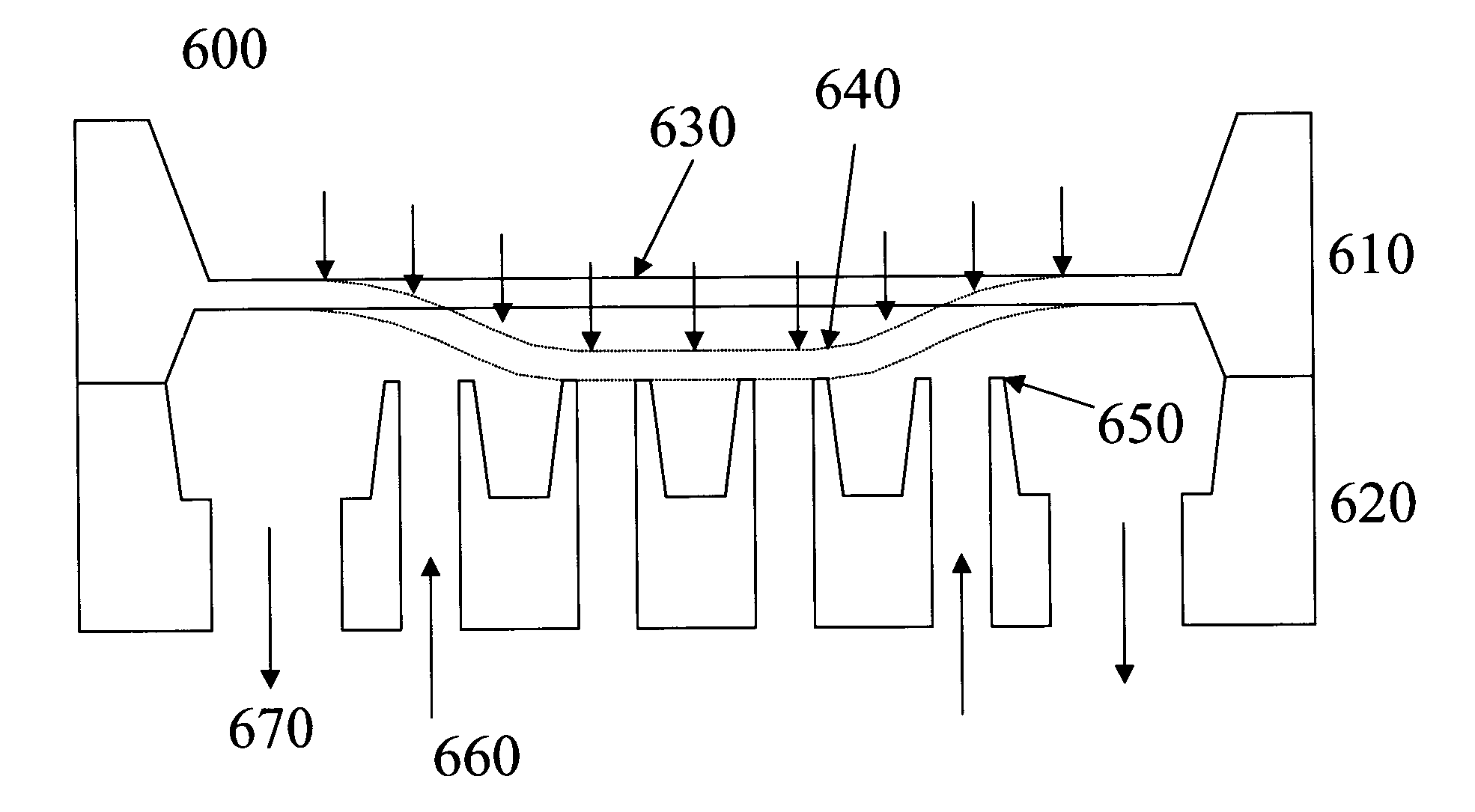
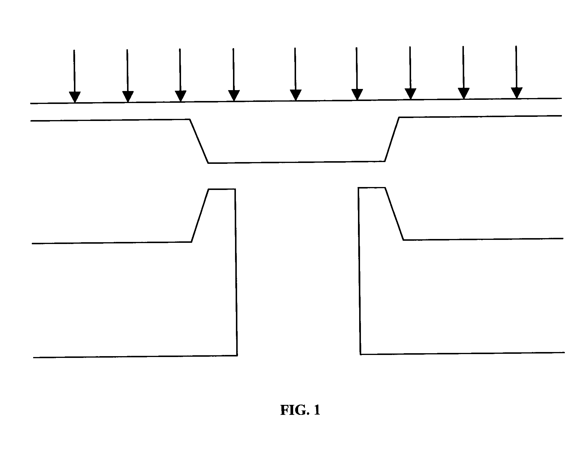
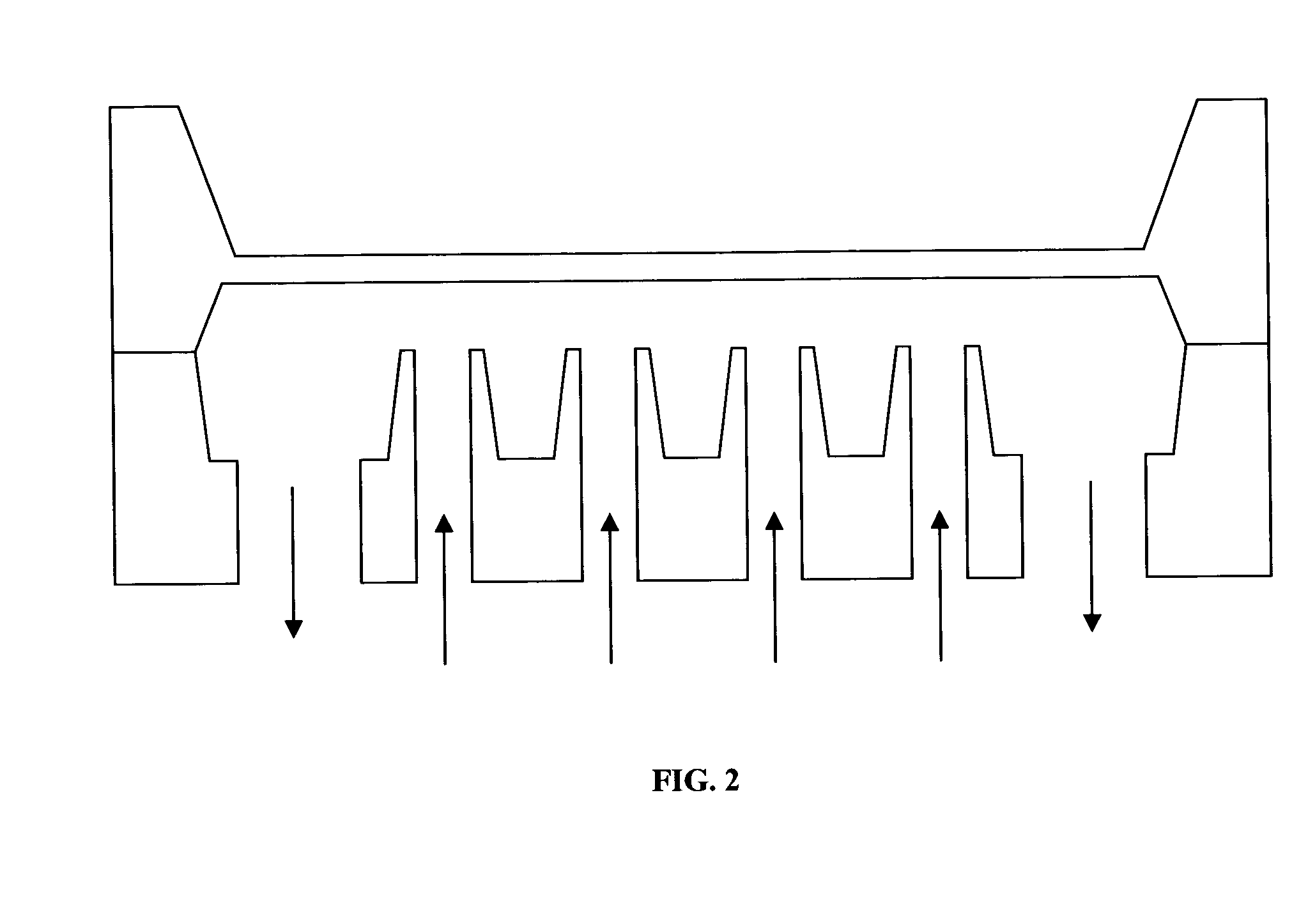
[0028]This invention discloses a method of designing valves which achieve high flow by maximizing the ratio of valve seat periphery length to a linear parameter equal to the square root of the area enclosed by the valve seat periphery. A preferred structure for a given valve seat area is also disclosed. This flow maximization also minimizes the gap between the actuator and the valve seat, corresponding to a desired maximum flow. As such, these valve designs presume valve operation in the gap height controlled regime, where the gap is less than one-half the radius of the combined valve seat opening. However, as the valve flow model indicates, this classical situation does not always hold. Orifice-controlled flow must also be considered. The transition from gap-controlled to orifice-controlled flow is a function of the actual design parameters of the valve, making the full flow model, given below, essential.

[0029]By maximizing the flow for a given constraint on the valve seat area, th...


PUM


Abstract

A method for achieving high flow in valves with small actuation distance is described. A detailed description for a silicon microvalve is provided. An algorithm is described for designing optimized valves.

Description

FIELD OF INVENTION[0001]The invention relates to the field of micromachined microvalves and more particularly to a microvalve for controlling high flows of fluids.BACKGROUND OF INVENTION[0002]The notion of a ‘microvalve’ rejects, on the surface, its use for high-flow applications in industrial process fluid distribution and control. Mass flow controllers (MFCs) in semiconductor processing require gas flows up to 50 standard liters per minute (slm). And, gas or liquid chromatography instruments can require similar sorts of flows. Refrigerators require liquid flows up to 12 cubic centimeters per minute (ccm), equivalent to perhaps 12 slm of gas flow. Manifold air flow applications in automobile engines also require high air flow to optimize vehicle motor efficiency and power. Requirements for control of high-purity fluids, proportional flow control, and for fast response, raise additional barriers to the use of microvalves in such high-flow applications.[0003]U.S. Pat. No. 4,538,642 [...

Claims


Application Information

Patent Timeline
Patent Type & Authority Patents(United States)
IPC IPC(8): F16K1/42F15C5/00F16KF16K11/04F16K99/00
CPCF15C5/00F16K99/0001F16K99/0009F16K99/0015F16K99/0036F16K99/0044F16K99/0059F16K99/0028F16K2099/0076Y10T137/86718Y10T137/86734
Inventor HENNING, ALBERT K.SELSER, MICHAELCOZAD, BRADFORD A.
Owner SMC CORP
Why Eureka
Try Eureka