Multiple feed brake caliper

a brake caliper and multi-feed technology, applied in the direction of cycle brakes, fluid actuated brakes, cycle equipment, etc., can solve the problems of ineffective and erratic braking, uncontrolled skid, and inconvenient pressure allocation for trikes, etc., to achieve simple, safe and inexpensive

Inactive Publication Date: 2006-01-17
LEISURE PROD
View PDF9 Cites 12 Cited by
  • Summary
  • Abstract
  • Description
  • Claims
  • Application Information

AI Technical Summary

Benefits of technology

[0011]What is needed is a simple, safe, and inexpensive motorcycle brake system modification for motorcycle conversions that preserves the advantages of the motorcycle's original linked braking control systems, requires no changes to the original master cylinders or front braking systems, and provides a means for optimizing the front-to-rear allocation of braking pressure.

Problems solved by technology

However, relatively unskilled motorcycle operators often instinctively rely too heavily on the rear brake to stop the motorcycle, resulting in an uncontrolled skid.
Unfortunately, that pressure allocation is usually not suitable for a trike.
Diverting extra braking pressure to the front wheel of a trike may result in ineffective and erratic braking and may in some cases destabilize the vehicle.
Some modification to the braking system of a trike conversion is clearly needed, but since modifications to the original motorcycle brake master cylinders and control systems are both cost-prohibitive and likely to raise complex engineering and safety issues, most modifications known in the art have relied on various ways of connecting, disconnecting, or redirecting the master cylinder outputs.
This modification provides no ability to optimize the front-to-rear braking pressure allocation and often produces an odd “feel” to the brake foot pedal, causing the pedal to “drop” and the trike to roll backward slightly once the vehicle has stopped and the braking pressure has eased.
This modification allows more even pressure distribution, but greatly reduces available braking force and user control while still providing no effective means for optimizing braking pressure distribution.
Although this approach preserves available braking pressure and operator control, it negates the safety features provided by linked control systems.

Method used


Image

  • Multiple feed brake caliper
  • Multiple feed brake caliper
  • Multiple feed brake caliper

Examples


Embodiment Construction

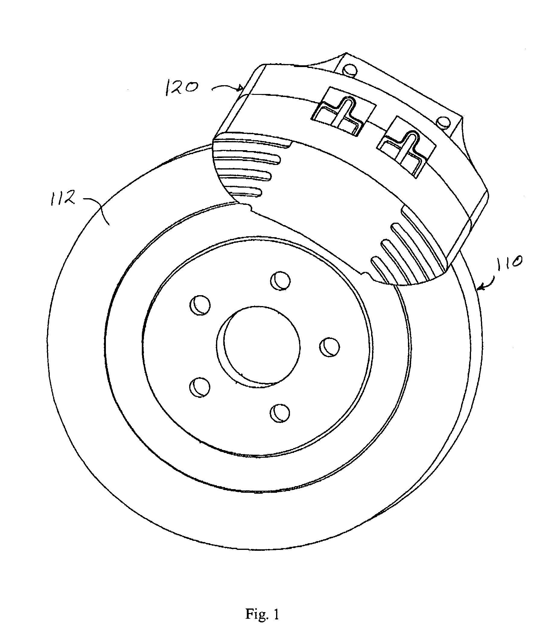
[0026]FIG. 1 shows a disk brake rotor and caliper. The rotor 110 is mounted on a rotating hub (not shown) that is mounted on an axle (not shown) that rotates within an upright (not shown). The hub, axle, and upright are known in the art and are not subjects of the present invention. The rotor 110 is a disk with an outer annular friction surface 112 facing away from the upright and with a substantially identical inner annular friction surface (not shown) facing toward the upright. A brake caliper 120 is mounted on the upright so that the rotor 110 may pass through a portion of the brake caliper 120 as the rotor 110 turns.

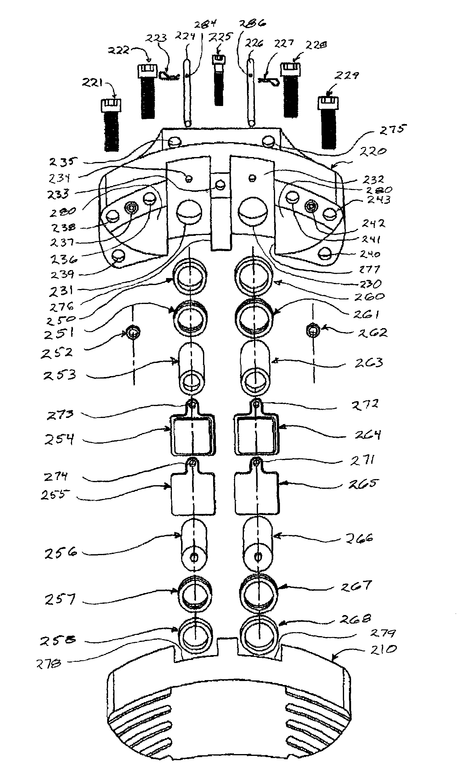
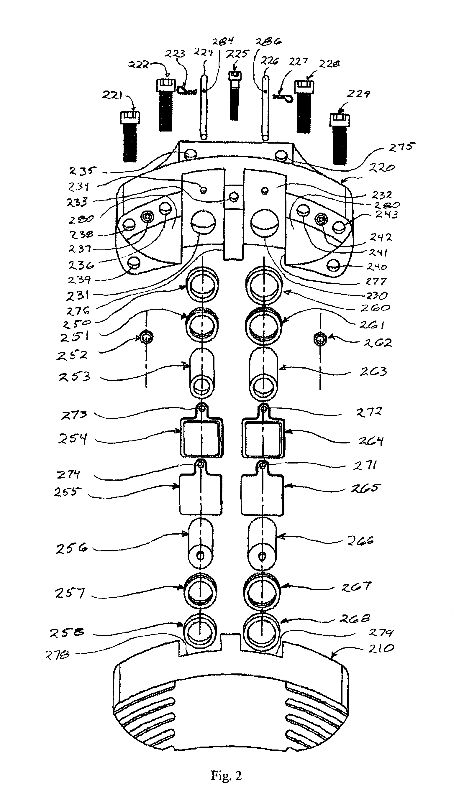
[0027]FIG. 2 shows an exploded view of a preferred embodiment of the brake caliper of the present invention. An outer caliper half 210 is fastened to an inner caliper half 220 by fasteners 221, 222, 225, 228, 229, each fastener passing through a hole 238, 236, 233, 241, 243 (respectively) drilled through the inner caliper half to screw into corresponding threaded hol...


PUM


Abstract

A disc brake caliper for conversion of a motorcycle with a linked braking system to a trike integrates two or more separate sets of opposed braking cylinders and pads within a single housing. Braking cylinder sets are not connected to other braking cylinder sets within the housing. Each set of braking cylinders is connected to and actuated independently by a different master cylinder. At least two braking cylinder sets within a housing have different diameters, the diameters of each set being chosen to produce a desired amount of braking pressure in response to an expected amount of hydraulic pressure from a master cylinder actuating the set. Both the diameter of each braking cylinder set and ratio of diameters between different braking cylinder sets are chosen to produce the optimum rear wheel braking pressure allocation for a given braking control system and vehicle configuration with no changes to the master cylinders or the front wheel braking system.

Description

CROSS-REFERENCE TO RELATED APPLICATIONS[0001]None.BACKGROUND AND SUMMARY[0002]Motorcycle enthusiasts number in the hundreds of thousands. Many riders, especially those who enjoy long-distance touring, prefer the power and stability of large touring bikes. To gain additional stability and load-carrying capacity, a sizeable minority have opted to convert their two-wheeled motorcycles to three-wheeled vehicles, or “trikes.”[0003]In such a conversion most of the systems of the motorcycle are typically retained except for the rear portions of the drive train, the rear suspension, and the rear brake system. However, since the handling characteristics of a three-wheeled vehicle are very different than those of a two-wheeled vehicle, some modifications are needed to allow safe and comfortable operation of the vehicle.[0004]Safe and effective modifications to the brake system are especially critical. Motorcycles have traditionally employed a foot pedal to actuate the rear brake and a hand le...

Claims


Application Information

Patent Timeline
Patent Type & Authority Patents(United States)
IPC IPC(8): F16D55/18B62L3/08F16D55/228F16D65/14
CPCB62L3/08F16D55/228F16D2125/06F16D2055/0091
Inventor SIMMONS, WALTER JOSEPHWOOLUM, WILLIAM DALE
Owner LEISURE PROD
Why Eureka
Try Eureka