Spring holding cone for holding a spring end of a spiral torsion spring

Inactive Publication Date: 2006-01-17
WILHELM BRAND KG
View PDF13 Cites 7 Cited by
  • Summary
  • Abstract
  • Description
  • Claims
  • Application Information

AI Technical Summary

Benefits of technology

[0010]The new spring holding cone comprises the flank on the outside surface only over a limited part of its circumference. Thus, the first spring turn of the unloaded torsion spring may be easily pressed over the flank, or it is at least easily possible to screw the flank between the first and the second spring turn. A spring end may be fixed to the new spring holding cone in a torque resistant way by means of a torque transfer leg projecting from the torsion spring in a radial direction. Such a torque transfer leg can be provided with relatively little expense in the manufacture of the torsion spring by bending over the last part of the spring wire. In no case it is necessary to form the torque transfer leg on the spring holding cone after the spring end has been attached to the cone. Rather, the torque transfer leg is just brought into the recess of the fixing means, where it abuts against the stopping face in transferring torque. Thus, the torque is transferred in the new spring holding cone between the torque transfer leg and the stopping face in a positive way, i.e. not or not only by means of friction.
[0017]Further, it is preferred that the outside surface conically increases in size, and that it is roughened. The conical outside surface, against which the torsion spring abuts under torsion load due to, its reduction in its inside diameter is preferably roughened to the end that the spring turns do not slip off from the outside surface in applying torsion load to the torsion spring, and that a uniform running behaviour of the spring turns in the transitional area at the end of the spring holding cone within the torsion spring is guaranteed. Alternatively, the outside surface can comprise a diameter which is increasing not steadily but step by step.

Problems solved by technology

A disadvantage of this known spring holding cone is that it does not hold the spring end positively but only non-positively, i.e. by means of friction between the cone and the spring wire, and that the expenditures for installing the spring end on the spring holding cone are quite high.
As a result, the expenses for attaching the spring holding cone to a torsion spring are very high.
In smaller production series this reduces the utilization of tools for forming the spring holding cones.

Method used


Image

  • Spring holding cone for holding a spring end of a spiral torsion spring
  • Spring holding cone for holding a spring end of a spiral torsion spring
  • Spring holding cone for holding a spring end of a spiral torsion spring

Examples


Embodiment Construction

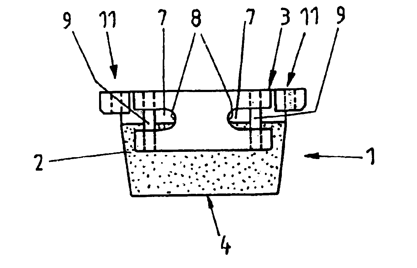
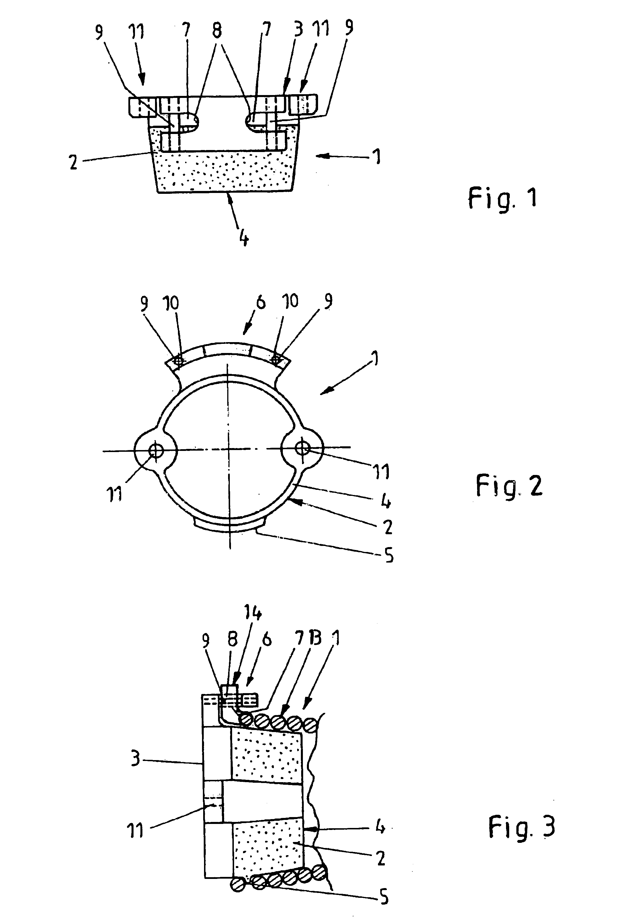
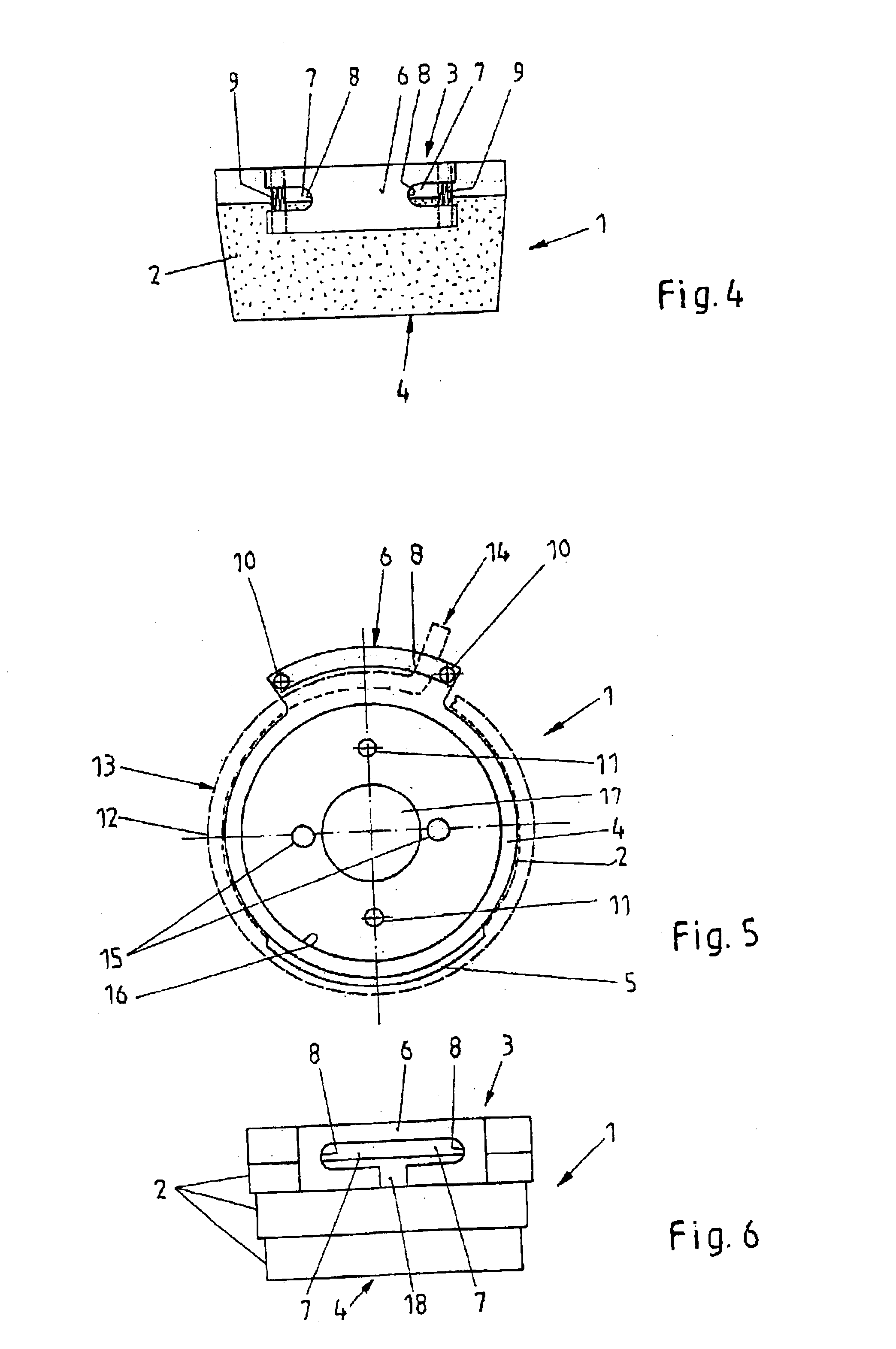
[0029]The spring holding cone shown in FIGS. 1 to 3 has an outside surface 2 conically increasing in diameter. The circumference of the outside surface 2 increases towards a free end 3 of the spring holding cone 1, which is located opposite to an end 4, which is to be inserted in a spring end of a torsion spring. The torsion spring is pushed onto the outside surface 2 until a flank 5, which projects from the outside surface 2, engages between the first and the second spring turn. This can be effected in that the first spring turn is pressed over the flank 5, or that the flank 5 is screwed in between the first and the second spring turn. A securing element 6, which “overhangs”, i.e. extends above, the outside surface 2 in a flank-free area, is provided diametrically opposite to the flank 5. Two recesses 7 are provided in the securing element 6 which may accept a torque transfer leg to which the end of the spring wire of the torsion spring is bent in a radial outward direction. The cr...


PUM


Abstract

A spring holding cone (1) for a spring end of a spiral torsion spring (13), especially a sectional door spring for an industrial door or a garage sectional door, has an outside surface (2) for supporting the spring end of the torsion spring (13) at its inside diameter and fixing means for fixing the spring end to the spring holding cone (1) in a torque resistant way. The fixing means comprise a flank (5) which protrudes from the outside surface (2) and engages between the first spring turn (12) and the second spring turn of the torsion spring (13) at the spring end. The flank (5) extends over less than 180° of the circumference of the outside surface (2); and a securing element (6) extends over a flank-free area of the outside surface (2). The securing element (6) has a recess for holding a torque transfer leg (14) projecting in a radial direction from the torsion spring (13); and the recess is limited in at least one tangential direction around the circumference of the outside surface (2) by a stopping face for the torque transfer leg (14).

Description

CROSS REFERENCE TO RELATED APPLICATIONS[0001]This application claims priority to co-pending European Patent Application No. 02 001 723.3 entitled “Federaufnahmekonus für ein Federende einer spiralformigen Torsionsfeder”, filed Jan. 25, 2002.FIELD OF THE INVENTION[0002]The invention generally relates to a spring holding cone for holding a spring end of a spiral torsion spring. Particularly, the invention relates to a spring holding cone for holding a spring end of a sectional door spring for an industrial door or a garage sectional door. Such a spring holding cone has an outside surface for supporting the torsion spring at its inside diameter and fixing means for fixing the spring end to the spring holding cone in a torque resistant way, the fixing means comprising a flank which protrudes from the outside surface and engages between the spring turns of the torsion spring at the spring end.BACKGROUND OF THE INVENTION[0003]In sectional doors torsion springs serve for compensating for t...

Claims


Application Information

Patent Timeline
IPC IPC(8): F16F1/06E05F1/08F16F1/12
CPCE05D13/1261F16F1/127F16F1/125E05Y2900/106E05Y2900/11
Inventor ALERS, JURGENBIRWE, JOCHEN
Owner WILHELM BRAND KG
Why Eureka
Try Eureka