Method and apparatus for determining message response type in a security system

a message response and security system technology, applied in the field of security systems, can solve the problems of affecting the ability of the control panel to service signals, affecting the service of motion detector devices, and large amount of unnecessary signal traffi

Inactive Publication Date: 2006-01-17
ADEMCO INC
View PDF6 Cites 62 Cited by
  • Summary
  • Abstract
  • Description
  • Claims
  • Application Information

AI Technical Summary

Benefits of technology

[0017]This second aspect of the invention thereby allows the control panel to determine if a message received from a...

Problems solved by technology

The first problem is caused by wireless security systems that utilize a large number of wireless motion detector transmitters.
When the security system is in the armed state, these motion detector devices are not activated due to the lack of people moving about in the protected premises.
However, when the security system is in the disarmed state, these motion detector devices are constantly transmitting signals to the associated RF receivers due to their detection of people moving within the protected premises while the control panel is disarmed.
However, the frequent signal transmissions from these types of transmitters cause a large amount of unnecessary signal traffic on the wired communication bus connecting the control panel to the RF receivers.
In effect, these unnecessary signal transmissions hamper the ability of the control panel to service signals transmitted from other devices, wired and wireless, which need immediate attention even when the system is disarmed.
The second problem found in large wireless security systems relates to the use of a large number of wireless receivers in a system that are connected to the control panel.
That is, this limitation is restric...

Method used


Image

  • Method and apparatus for determining message response type in a security system
  • Method and apparatus for determining message response type in a security system
  • Method and apparatus for determining message response type in a security system

Examples


Embodiment Construction

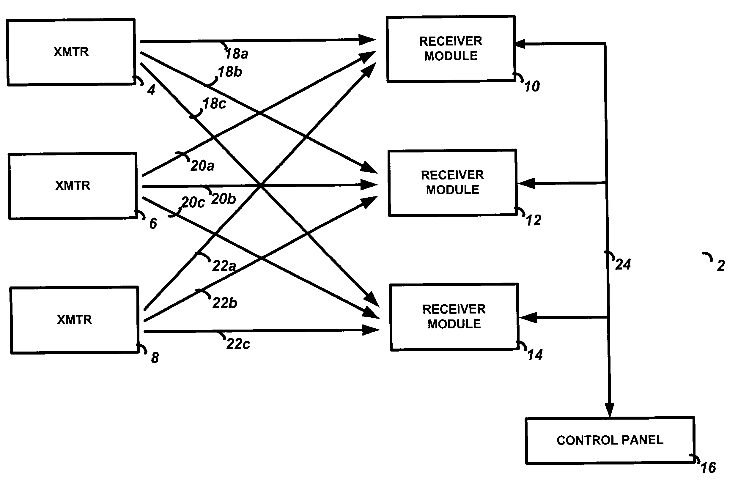
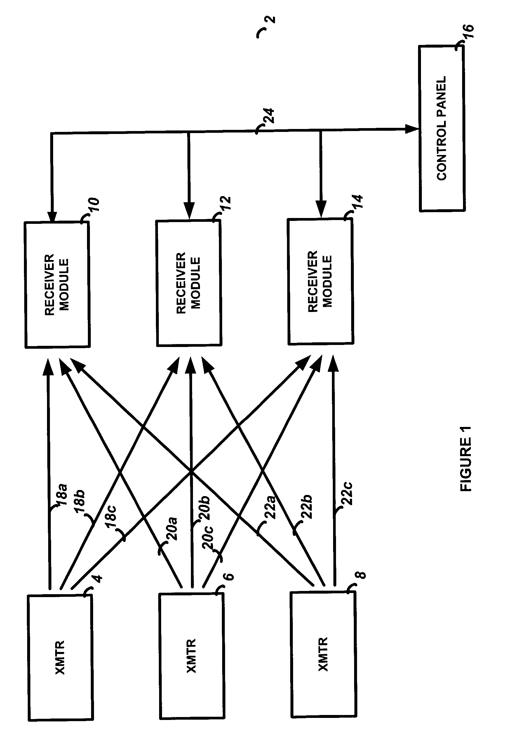
[0032]The preferred embodiment of the present invention will now be described with respect to the Figures. FIG. 1 illustrates a block diagram of the preferred embodiment wireless security system of the present invention. A security system 2 is shown, which includes a number of wireless transmitters 4, 6, and 8. The transmitters 4, 6, and 8 are associated with various types of alarm or security detectors such as motion sensors, door status detectors, smoke alarms, and the like, which operate to monitor a condition of the premises and send status messages to the control panel via the wireless transmitter / receiver module pair. Specific characteristics of these various detectors are not shown here for the sake of clarity, but are well known in the art of security systems. Many transmitters are likely used in the security system 2 as may be required by a particular application; only three such transmitters are shown in FIG. 1 for the sake of clarity.

[0033]Wireless receiver modules 10, 12...


PUM


Abstract

A security system with wireless transmitters, a wireless receiver, and a control panel. A wireless message, which includes a transmitter product type, is received from the wireless transmitter. The control panel extracts the transmitter product type from the wireless message and then determines a response type to be performed as a function of the transmitter product type. A response to the wireless message is then executed in accordance with the determined response type. The response type may be determined by the control panel by using the transmitter product type to lookup an associated response type in a response type table at the control panel. The wireless message also includes a unique identification number, and the transmitter product type may be a separate field from the unique identification number or it may be integral with the unique identification number. The unique identification number is initially programmed in the wireless transmitter by assigning the product type portion as a function of the transmitter type.

Description

CROSS-REFERENCE TO RELATED APPLICATIONS[0001]This application is related to co-pending U.S. applications Ser. No. 10 / 264,329 entitled METHOD AND APPARATUS FOR FILTERING NON-ESSENTIAL MESSAGES IN A DISARMED SECURITY SYSTEM; Ser. No. 10 / 264,214 entitled METHOD AND APPARATUS FOR PROVIDING A MESSAGE SEQUENCE COUNT IN A SECURITY SYSTEM; and Ser. No. 10 / 263,625, now U.S. Pat. No. 6,690,276 entitled METHOD AND APPARATUS FOR MONITORING MESSAGE ACKNOWLEDGEMENTS IN A SECURITY SYSTEM; all of which were filed contemporaneously on even date herewith.FIELD OF THE INVENTION[0002]This invention relates to security systems, and in particular to a method and system for a control panel to initiate a response to a wireless message based on the type of transmitter from which the message was transmitted.BACKGROUND OF THE INVENTION[0003]The present invention addresses several problems found in large wireless security systems. The first problem is caused by wireless security systems that utilize a large nu...

Claims


Application Information

Patent Timeline
IPC IPC(8): G08B1/08G08B25/10
CPCG08B25/006G08B25/10G08B25/007G08B25/003
Inventor MARINO, FRANCIS C.ADDY, KENNETH L.
Owner ADEMCO INC
Why Eureka
Try Eureka