
Image processing method and apparatus

a technology of image processing and image, applied in the field of image processing methods and apparatuses, can solve the problems of inability to achieve color matching corresponding to ambient light, inability to guarantee correct color reproduction, etc., and achieve the effect of excellent color reproduction

Inactive Publication Date: 2006-01-17
CANON KK
View PDF22 Cites 23 Cited by
  • Summary
  • Abstract
  • Description
  • Claims
  • Application Information

AI Technical Summary

Benefits of technology

[0015]Another object of the present invention is to provide an image processing method and apparatus for realizing excellent color reproduction particularly by performing partial adaptation processing.
[0016]Furthermore, another object of the present invention is to provide an image processing method and apparatus which enable adjustment of partial adaptation processing so as to adjust chromatic adaptability processing to obtain a result desired by a user.

Problems solved by technology

Under an illuminant of other characteristics, correct color reproduction is not guaranteed.
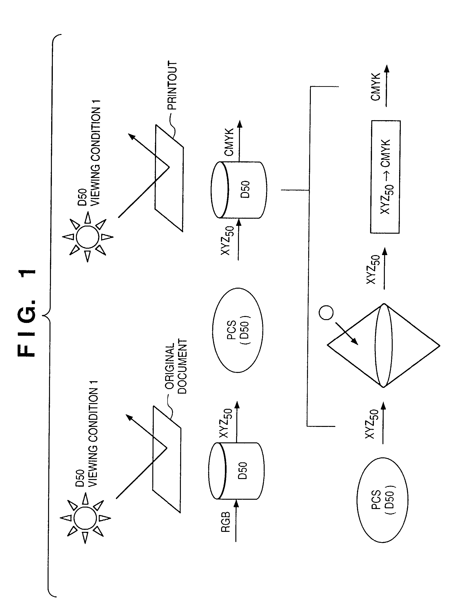
Moreover, in the current ICC profile, since the PCS is limited to XYZ values or Lab values based on D50 characteristic, color matching corresponding to ambient light cannot be performed.

Method used


Image

  • Image processing method and apparatus
  • Image processing method and apparatus
  • Image processing method and apparatus

Examples


first embodiment

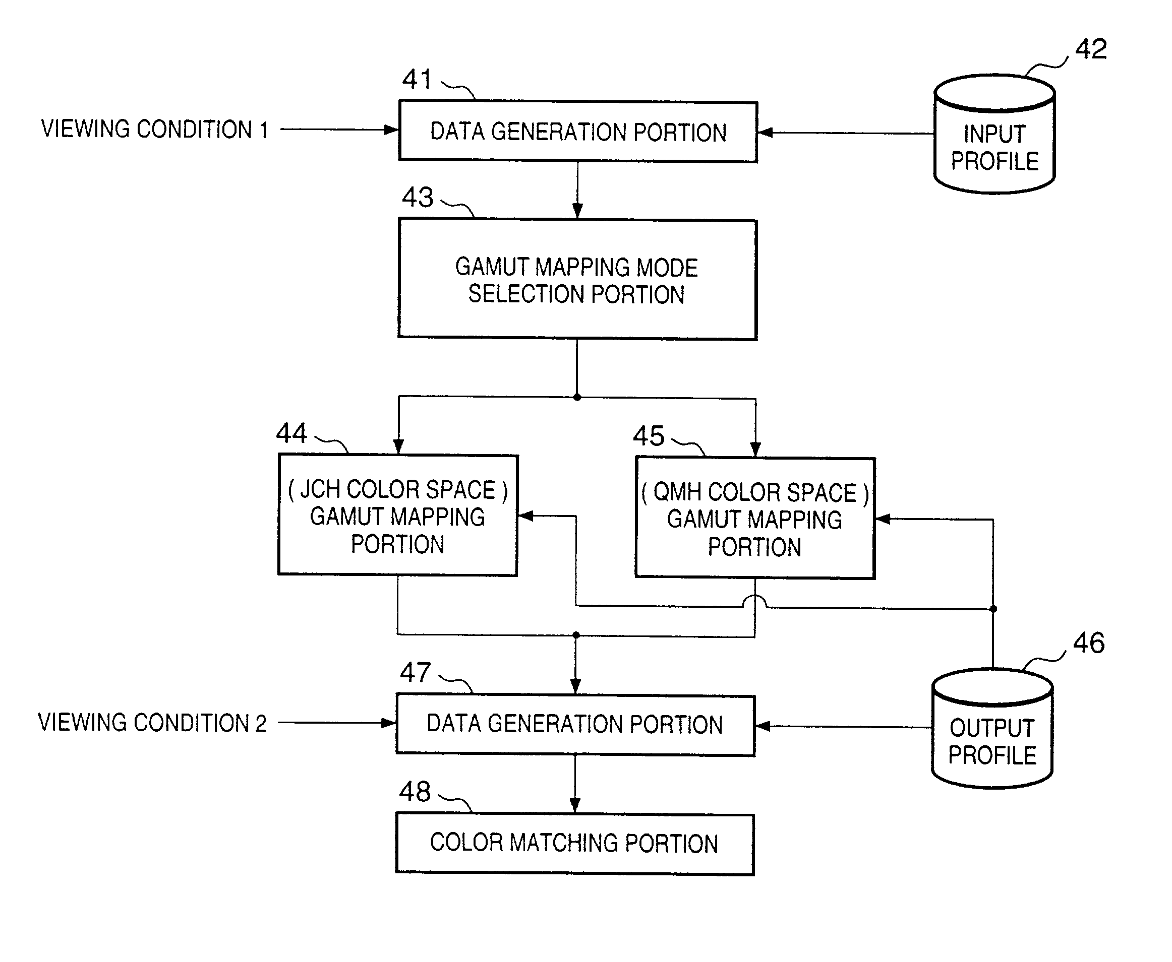
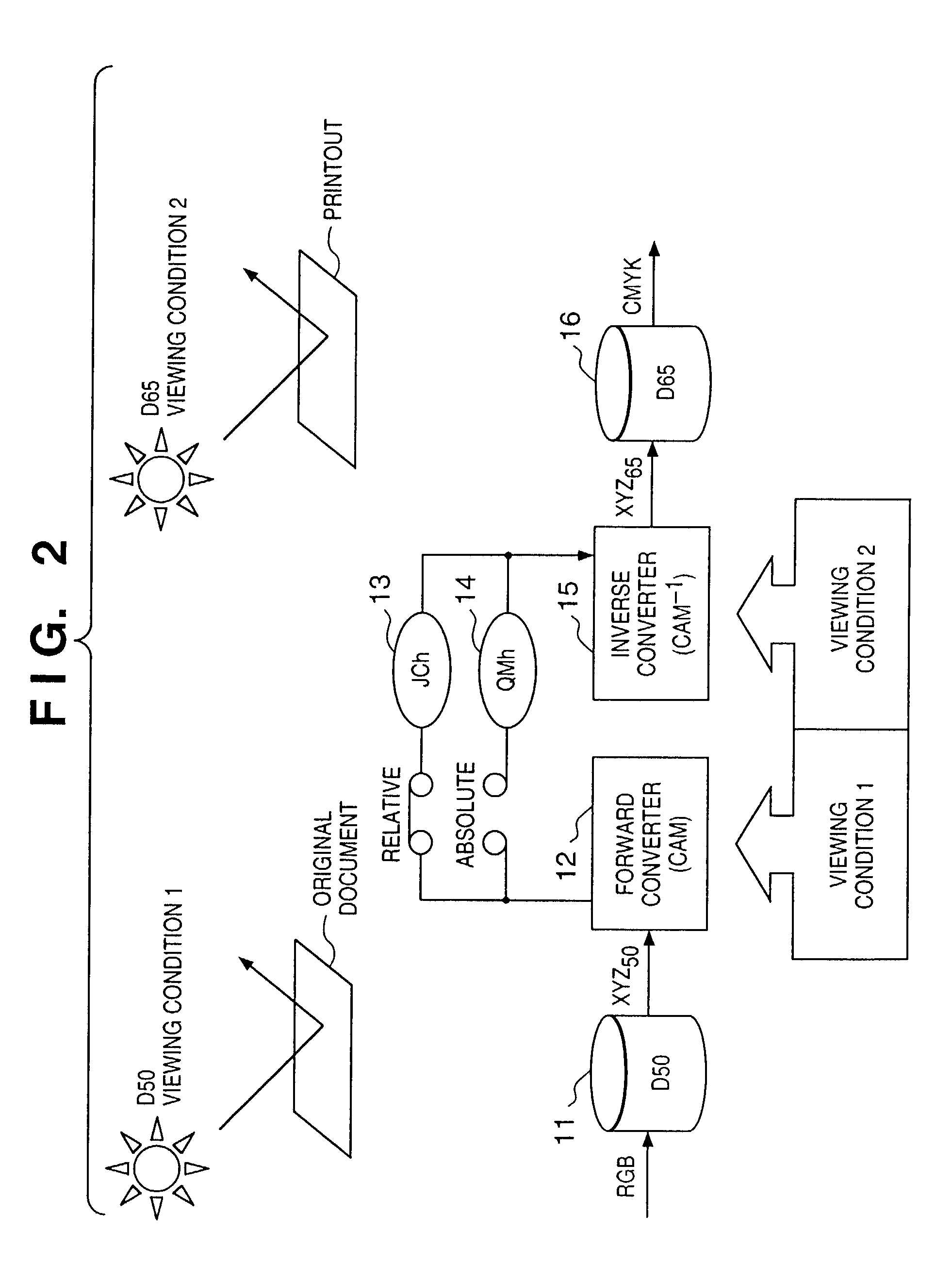
[0063]Description is provided for the first embodiment in which a profile is dynamically changed in accordance with a viewing condition.

[0064]Referring to FIG. 2, reference numeral 11 denotes a conversion matrix or a conversion lookup table (LUT) for converting data which is dependent on an input device (hereinafter referred to as input-device-dependent data) to data of the device-independent color space (hereinafter referred to as input-independent data), which accords to a white point of ambient light at the time of viewing an image formed on an original. Reference numeral 12 denotes a forward converter (CAM) of a color perception model for converting data, obtained from the conversion LUT 11, to human color perception color space JCh or QMh. Reference numeral 13 denotes a relative color perception space JCh (or JCH) relative to the reference white of an ambient light; and 14, an absolute color perception space QMh (or QMH) whose size changes in accordance with an illuminance leve...

third embodiment

[0149]Described in a third embodiment is an example of a Graphic User Interface (GUI) for manually setting a viewing condition (e.g., viewing condition 1 or 2 in FIG. 2) for each of the foregoing embodiments.

[0150]FIG. 19 shows a GUI 191 for setting a parameter of a viewing condition according to the third embodiment.

[0151]Reference numeral 213 denotes a drop-down combo-box for setting a viewing subject on the input side (i.e., input device); 217, a drop-down combo-box for setting a viewing subject on the output side (i.e., output device); 214, a text box for inputting a luminance of a viewing subject on the input side; 215, a drop-down combo-box for selecting the type of white point in the viewing subject on the input side; 216, a drop-down combo-box for selecting a viewing condition on the input side; 218, a text box for inputting a luminance of a viewing subject on the output side; 219, a drop-down combo-box for selecting a white point in the viewing subject on the output side; a...


PUM


Abstract

If gamut mapping (hue restoration) defined by one Lab color space is applied in color matching under different reference white points, the human vision perceives the hue as inconsistent. In view of this, input data which is dependent on a color space of an input device is converted by the conversion LUT 11 to color space data which is independent of any devices, based on a viewing condition at the time of viewing an input original. The data is converted to data in the human color perception space by the forward converter 12, then subjected to gamut mapping, and converted back to data in the color space independent of any devices by the inverse converter 15, based on a viewing condition at the time of viewing an output original. Then, the data is converted to output data in a color space which is dependent on an output device by the conversion LUT 16.

Description

[0001]This application is a division of application Ser. No. 09 / 437,322, filed on Nov. 10, 1999 now U.S. Pat. No. 6,459,436.BACKGROUND OF THE INVENTION[0002]The present invention relates to an image processing method and apparatus, and more particularly, to an image processing method and apparatus for performing color matching according to ambient light.[0003]FIG. 1 is a conceptual view of general color matching.[0004]Input RGB data is converted by an input profile to XYZ data of a color space which does not depend on any devices. Since an output device cannot express colors outside the color reproduction range of the output device, gamut mapping is performed on the inputted data, which has been converted to the data in the device-independent color space, such that all colors of the inputted data fall within the color reproduction range of the output device. After the gamut mapping is performed, the inputted data is converted from the device-independent color space to CMYK data of a...

Claims


Application Information

Patent Timeline
IPC IPC(8): G09G5/02G06T1/00H04N1/46H04N1/60
CPCG09G5/02H04N1/6088H04N1/6086H04N1/6058G09G2320/0626
Inventor KUMADA, SHUICHIOHGA, MANABU
Owner CANON KK
Learn More