Large kappa dispersion compensating fiber and transmission system

a transmission system and fiber technology, applied in the field of optical fiber, can solve the problems of large dispersion problem, high data rate and broad bandwidth, and associated penalties, and achieve the effects of high kappa, good bend loss properties, and high effective area

Inactive Publication Date: 2006-01-17
CORNING INC
View PDF9 Cites 9 Cited by
  • Summary
  • Abstract
  • Description
  • Claims
  • Application Information

AI Technical Summary

Benefits of technology

[0022]The dispersion compensating fiber according to the invention has the advantage of having very high kappa. Also, such high kappa is achieved while preferably retaining high effective area (greater than or equal to 17 square microns at 1550 nm) and while preferably also retaining good bend loss properties. High effective area allows for less coupling loss, low nonlinearities, and reduced four wave mixing and cross phase modulation, and is thus desirable.

Problems solved by technology

These high data rates and broad bandwidths, however, have penalties associated with them.
In particular, dispersion is a significant problem in such systems.

Method used


Image

  • Large kappa dispersion compensating fiber and transmission system
  • Large kappa dispersion compensating fiber and transmission system
  • Large kappa dispersion compensating fiber and transmission system

Examples


examples

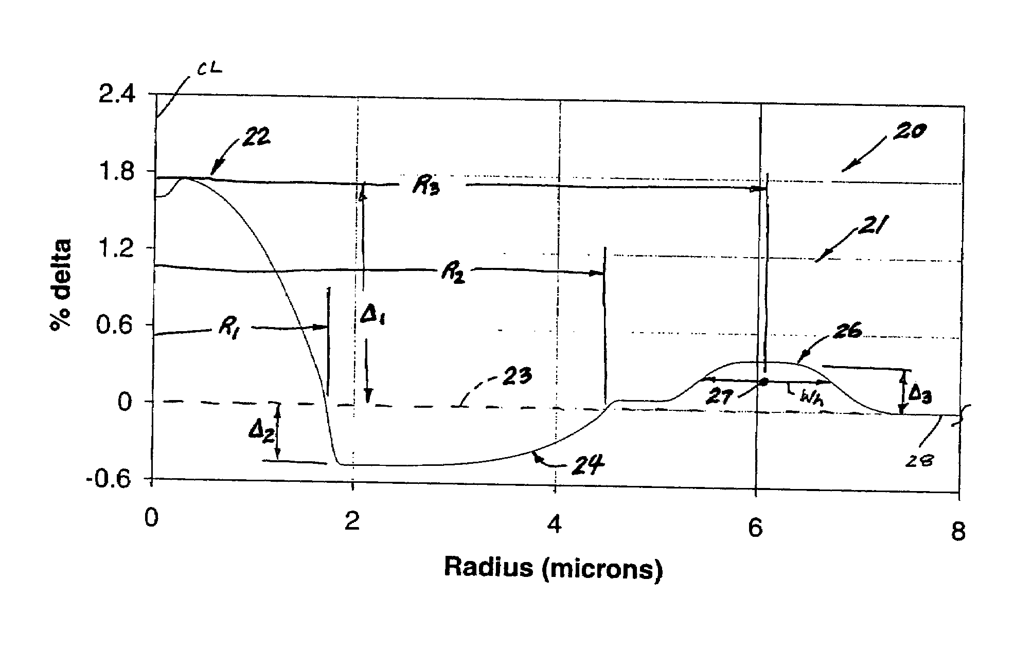
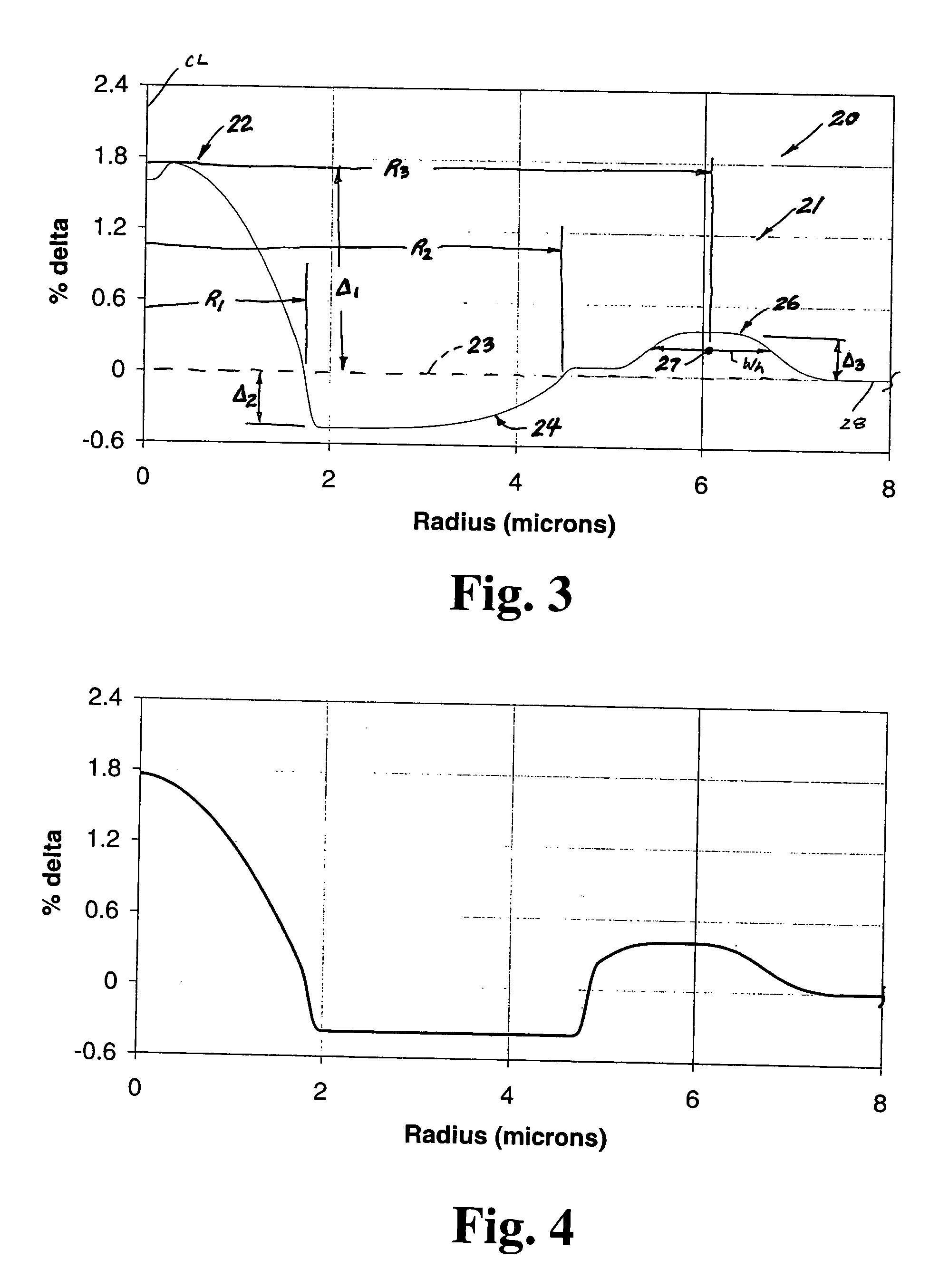
[0051]The present invention will be further clarified by the following examples summarized in Table 1 below. Table 1 includes optical attributes (such as Total Dispersion at 1550 and 1600 nm, Dispersion Slope at 1550 nm, Kappa at 1550 and 1600 nm, Kappa Ratio (KR) between kappa at 1550 nm and kappa at 1600 nm, Pin Array at 1550 nm, Lateral Load at 1550 nm, Effective Area at 1550 nm, and theoretical LP02 cutoff wavelength) as well as refractive index structural parameters (Δ1, Δ2, Δ3, R1, R2, R3, Ro, Wh, and Core-Moat ratio) for the dispersion compensating fibers 20 in accordance with the invention. Examples 1–6 directly correspond to FIGS. 3–8, respectively.

[0052]

TABLE 1Examples - Dispersion Compensation FiberDispersionKappa(ps / nm / km)Slope(nm)@ 1550 nm / (ps / nm2 / km)@ 1550 nm / Δ1Δ2Δ3R1R2R3Ex.@ 1600 nm@ 1550 nm@ 1600 nmKR%%%(μm)(μm)(μm)1−103 / −118−0.35296 / 4601.561.76−0.470.391.752.916.082 −90 / −103−0.29311 / 4961.591.77−0.390.411.863.195.833−116 / −133−0.36319 / 4891.532.06−0.430.351.642.955.704...


PUM


Abstract

A dispersion compensation fiber for a moderate dispersion, low slope transmission fiber and transmission system including same. The dispersion compensating fiber has a refractive index profile having a central core with a core delta (Δ1), a moat surrounding the central core having a moat delta (Δ2), and a ring surrounding the moat having a positive ring delta (Δ3). The fiber's refractive index profile is selected to provide total dispersion less than −80 at 1550 nm and less than −90 ps / nm / km at 1600 nm, dispersion slope less than −0.18 ps / nm2 / km at 1550 and less than −0.10 ps / nm2 / km at 1600 nm / kappa between 250 and 450 at 1550 nm, and a kappa ratio (defined as kappa at 1600 nm / kappa at 1550 nm) of greater than 1.35. The dispersion compensating fiber, when used in a transmission system, may provide low average residual dispersion across the C, L, and C+L bands when such systems include moderate dispersion, low dispersion slope transmission fibers with a total dispersion between 4 and 8 ps / nm / km, and a dispersion slope less than 0.025 ps / nm2 / km at all wavelengths between 1525 and 1625 nm.

Description

BACKGROUND OF THE INVENTION[0001]1. Field of the Invention[0002]The present invention relates generally to optical fiber, and more particularly to dispersion compensation fiber and transmission systems including coupled combinations of transmission fiber and dispersion compensation fiber.[0003]2. Technical Background[0004]Higher data rates and wider bandwidth systems are becoming needed for the telecommunications industry. Thus, the search for high performance optical fibers designed for long distance, high bit rate telecommunications that operate over broad bandwidths has intensified. These high data rates and broad bandwidths, however, have penalties associated with them. In particular, dispersion is a significant problem in such systems. More specifically, positive dispersion builds along the length of the high data rate transmission fiber. Dispersion compensating fibers included in cable or in dispersion compensation modules have been designed that compensate for such dispersion...

Claims


Application Information

Patent Timeline
Patent Type & Authority Patents(United States)
IPC IPC(8): G02B6/02G02B6/00G02B6/036H04B10/18
CPCG02B6/02004G02B6/02261G02B6/0228H04B10/2525G02B6/03644G02B6/03677G02B6/03688G02B6/0281
Inventor BICKHAM, SCOTT R.
Owner CORNING INC
Why Eureka
Try Eureka