Separator for flat-type polymer electrolyte fuel cells

a polymer electrolyte and fuel cell technology, applied in the direction of cell components, cell component details, electrochemical generators, etc., can solve the problems of complex processes, difficulty in forming wires, uneven fuel and oxygen feed from site to site, etc., to achieve high strength and improve power generation capability

Inactive Publication Date: 2011-10-18
DAI NIPPON PRINTING CO LTD
View PDF7 Cites 4 Cited by
  • Summary
  • Abstract
  • Description
  • Claims
  • Application Information

AI Technical Summary

Benefits of technology

[0012]A primary object of the invention is to provide a separator that is of reduced weight, and enables electrical series connections to be easily made between unit cells without increasing the internal resistance of a cell due to contact resistance.
[0017]According to the first aspect of the invention, when the fuel-feed-side separator and the oxygen-feed-side separator are bent toward each other and integrated together by the connecting hinges in such a way as to hold the membrane-electrode assembly (MEA) of the fuel cell between them, the lug members on the unit conductive substrates one of the separators that form one unit cell jut out in the adjoining cell region, and the lug members are joined by the connecting hinges to the unit conductive substrates of another separator in the adjoining unit cell, so that the n unit cells are placed in an electrically series connected state without recourse to wirings. It is thus possible to obtain a fuel cell that, because of absence of any contact resistance at connections, has a low internal resistance and is reduced in weight and thickness.
[0018]Another object of the invention is to provide a separator that makes it possible to obtain a slimmed-down polymer electrolyte fuel cell which is much reduced in contact resistance with unit cells having a high effective area factor.
[0026]According to the second aspect of the invention, the separator has so high strength that even when there is a swelling of the membrane-electrode assembly (MEA) in the flat-type polymer electrolyte fuel cell, the unit conductive substrates that form the separator is in reliable contact with the membrane-electrode assembly (MEA), ensuring uniform contact pressure. Thus, the flat-type polymer electrolyte fuel cell can have a high power generation capability with no or little contact resistance.
[0033]According to the invention as summarized above, the unit conductive substrates that form the separator are each configured in such a way as to jut toward the opening in the membrane-electrode assembly (MEA) side frame, so that even when there is a swelling of the membrane-electrode assembly (MEA) in the flat-type polymer electrolyte fuel cell, the unit conductive substrates work well against that swelling stress, imparting high strength to the separator and, hence, ensuring that the unit conductive substrates are in reliable, sustained contact with the membrane-electrode assembly (MEA). It is thus possible to achieve a flat-type polymer electrolyte fuel cell having an improved power generation capability with no or little contact resistance.

Problems solved by technology

With that flat-type wherein a plurality of unit cells are arrayed in flat configuration and electrically connected together in series, however, there is a problem that the feed of fuel and oxygen becomes uneven from site to site.
With that separator of such structure as explained above, however, there are problems such as difficulty with which wires are formed for making series connections between unit cells, complicated processes, and increased contact resistance due to wire connections.
With a prior art flat-type PEFC with the MEA put between the fuel-feed-side separator and the oxygen-feed-side separator as discussed above, there is another problem that as the MEA swells during power generation, it causes contact of the MEA with the fuel-feed-side separator or the oxygen-feed-side separator to become insufficient, resulting in an increased contact resistance.
However, provision of the width necessary for such tightening between the unit cells arrayed in flat configuration would arise yet another problem that the effective area of each unit cell diminishes.

Method used


Image

  • Separator for flat-type polymer electrolyte fuel cells
  • Separator for flat-type polymer electrolyte fuel cells
  • Separator for flat-type polymer electrolyte fuel cells

Examples


Embodiment Construction

[0057]Some embodiments of the invention are now explained with reference to the accompanying drawings.

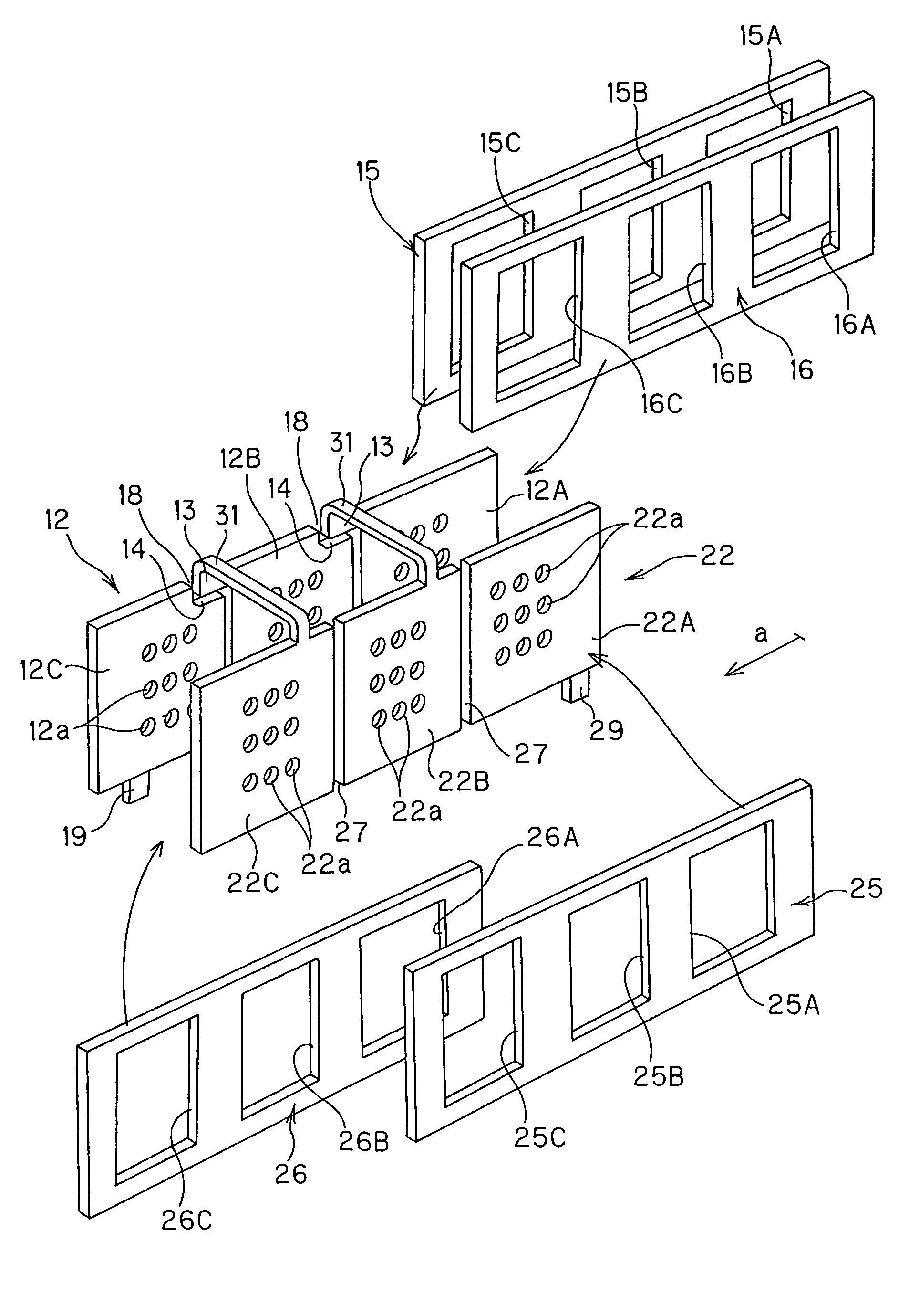
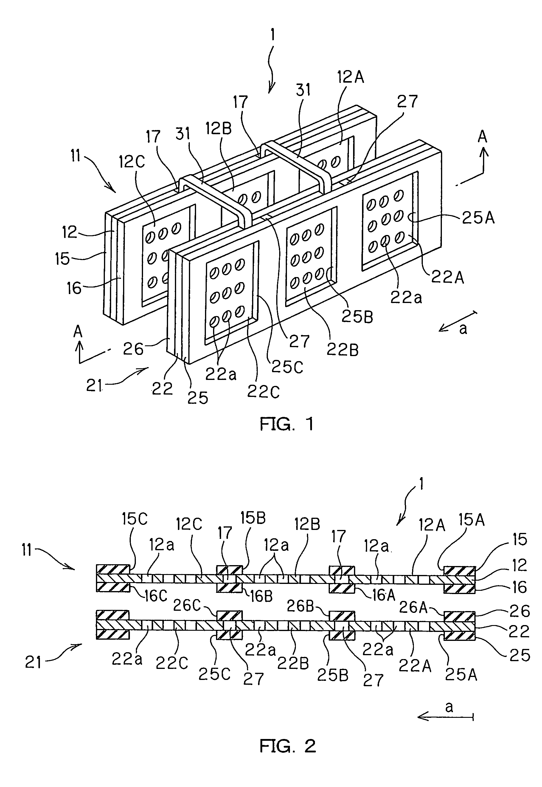
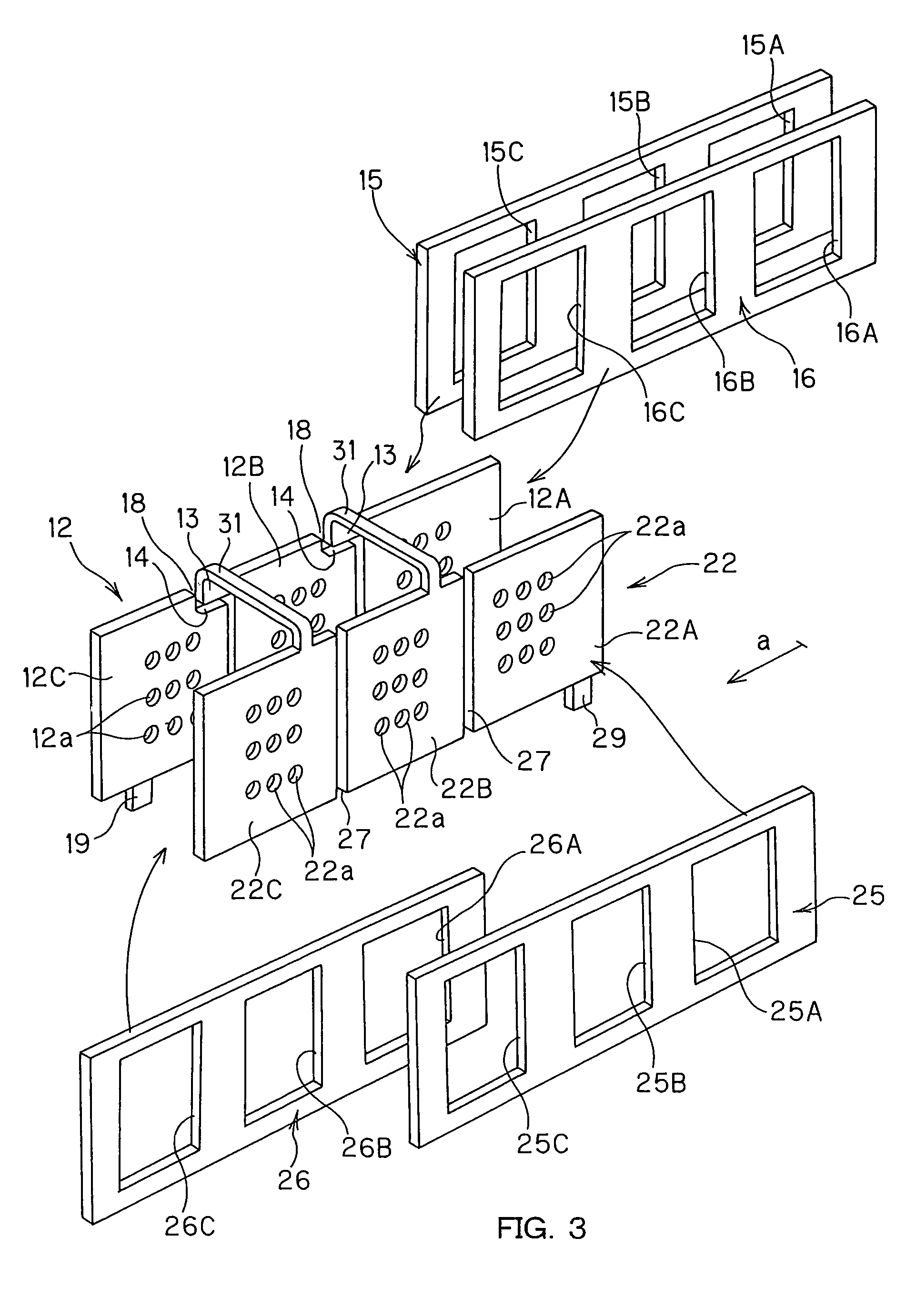
[0058]FIG. 1 is illustrative in perspective of the separator for a flat-type polymer electrolyte fuel cell according to the invention; FIG. 2 is illustrative in section of the separator depicted in FIG. 1, as taken on an A-A arrow section; and FIG. 3 is illustrative in perspective, as taken apart, of the components forming the separator depicted in FIG. 1. Referring to FIGS. 1-3, a separator 1 for the flat-type polymer electrolyte fuel cell according to the invention comprises a fuel-feed-side separator 11, and an oxygen-feed-side separator 21. For convenience of illustration here, the separator 1 is explained as the fuel-feed-side separator 11 and the oxygen-feed-side separator 21; however, it is understood that they are interchangeable. In FIGS. 1-3, it is also noted that the direction shown by an arrow a is the array direction of the unit conductive substrates to be described lat...


PUM

PropertyMeasurementUnit
thicknessaaaaaaaaaa
thicknessaaaaaaaaaa
opening diameteraaaaaaaaaa

Abstract

A separator for flat-type polymer electrolyte fuel cells comprises a fuel-feed-side separator and an oxygen-feed-side separator, each comprising a collector portion in which n unit conductive substrates (n is an integer of 2 or more), each having a plurality of through-holes, are arrayed in flat configuration via gaps, and a pair of insulating frames which have n openings in alignment with an array position of the unit conductive substrates and are integrated in such a way as to hold the collector portion between them. The back-to-back (n−1) unit conductive substrates of the n unit conductive substrates in one of both separators, as counted from the end of its array direction, and the 2nd to nth unit conductive substrates of the n unit conductive substrates in another separator, as counted from the end of its array direction are successively joined together by means of (n−1) connecting hinges.

Description

TECHNICAL FIELD[0001]The present invention relates generally to a separator for fuel cells, and more particularly to a separator for flat-type polymer electrolyte fuel cells.BACKGROUND ART[0002]Briefly, a fuel cell is a device wherein fuel (a reducing agent) and oxygen or air (an oxidizing agent) are continuously supplied to it from outside for electro-chemical reactions through which electric energy is taken out, and classified depending on its working temperature, the type of the fuel used, its applications, etc. Recently developed fuel cells are generally broken down into five types: a solid oxide type fuel cell, a molten carbonate type fuel cell, a phosphoric acid type fuel cell, a polymer electrolyte type fuel cell, and an alkaline aqueous solution type fuel cell, depending on kinds of using electrolytes.[0003]These fuel cells use hydrogen gas resulting from methane or the like as fuel. More recently, a direct methanol type fuel cell (sometimes abbreviated as DMFC) relying on d...

Claims


Application Information

Patent Timeline
Patent Type & Authority Patents(United States)
IPC IPC(8): H01M2/08H01M2/14H01M8/00H01M2/38
CPCH01M8/023H01M8/0273H01M8/242H01M8/0245H01M8/0276H01M2008/1095Y02E60/523Y02E60/50H01M8/2418H01M8/02H01M8/0297H01M8/2483
Inventor SERIZAWA, TOORUUCHIDA, YASUHIROMAEDA, TAKANORIYAGI, HIROSHI
Owner DAI NIPPON PRINTING CO LTD
Why Eureka
Try Eureka