
Dispersion optimized optical fiber for wideband optical transmission

a wideband optical transmission and optical fiber technology, applied in the field of optical fiber wideband transmission, can solve the problems of limiting higher bit rate transmission, single-mode fibers with very high dispersion loss, and low dispersion slope, and achieve low dispersion slope and high effective area. , the effect of low dispersion slop

Active Publication Date: 2008-10-14
STERLITE TECHNOLOGIES
View PDF14 Cites 1 Cited by
  • Summary
  • Abstract
  • Description
  • Claims
  • Application Information

AI Technical Summary

Benefits of technology

The fiber achieves low dispersion, low dispersion slope, high effective area, and reduced bending induced loss, enabling high-speed wideband transmission with no non-linearity issues, supporting multiple channel transmissions across the entire wavelength region, including the S-band, C-band, and L-band, and is suitable for metropolitan, long-haul, and ultra-haul network transmission systems.

Problems solved by technology

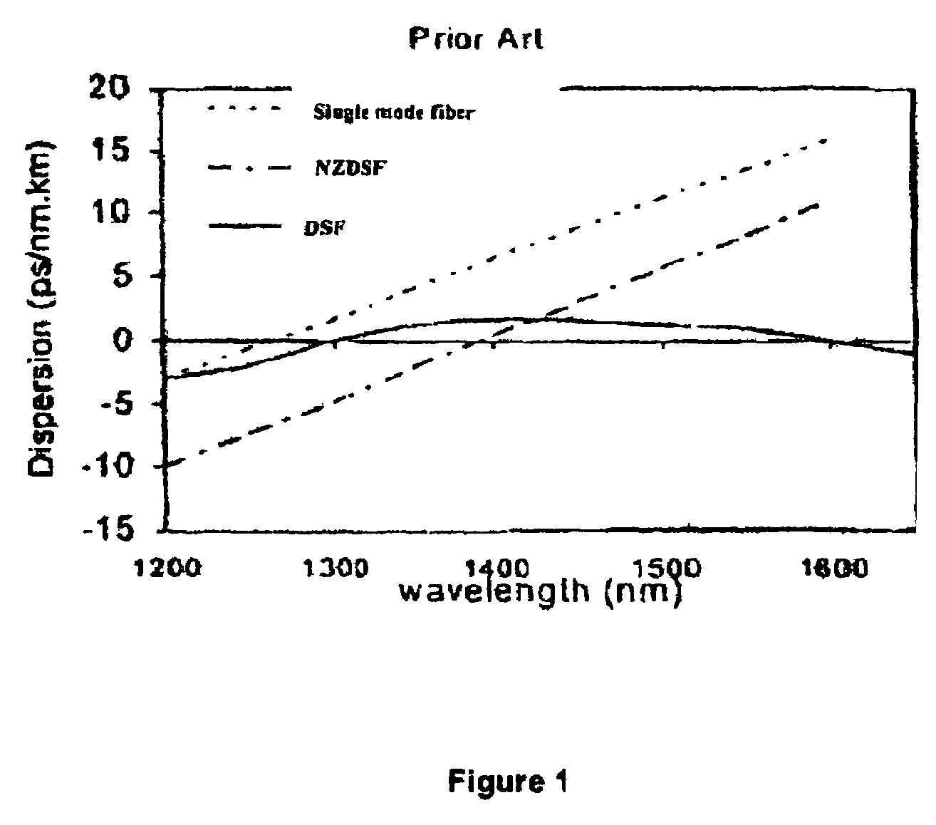
However, when single wavelength moved through 1550 nm window for lower attenuation loss, the single mode fibers were observed to have very high dispersion loss.
The major disadvantage of the single mode fibers with high dispersion loss at about 1550 nm was that it restricted higher bit rate transmission.
However, the dispersion shifted fibers used for long distance systems in the prior art have resulted in poor DWDM performance due to non-linear effects, for example, four wave-mixing, self phase modulation, cross phase modulation etc. caused by zero dispersion region within the DWDM window.
This result is strong four wave mixing, which prevents good DWDM performance.
The fibers as known in the prior art either have low non-linearity but high bend loss or have low bend loss but less effective area or may have, higher non-linearity and higher bend loss or may have non-uniform chromatic dispersion over the third and fourth window or high dispersion slope, that is the fibre will not have desired characteristic properties and will sacrifice one of the property for achieving another property.
The increasing complexity of the demands on the fiber makes the designer to think further to re-design the refractive index profile [relationship between refractive index of each part of the fiber].
This requires thinking to have more complex designs.
However, the complex designs are very sensitive to the manufacturing processes.
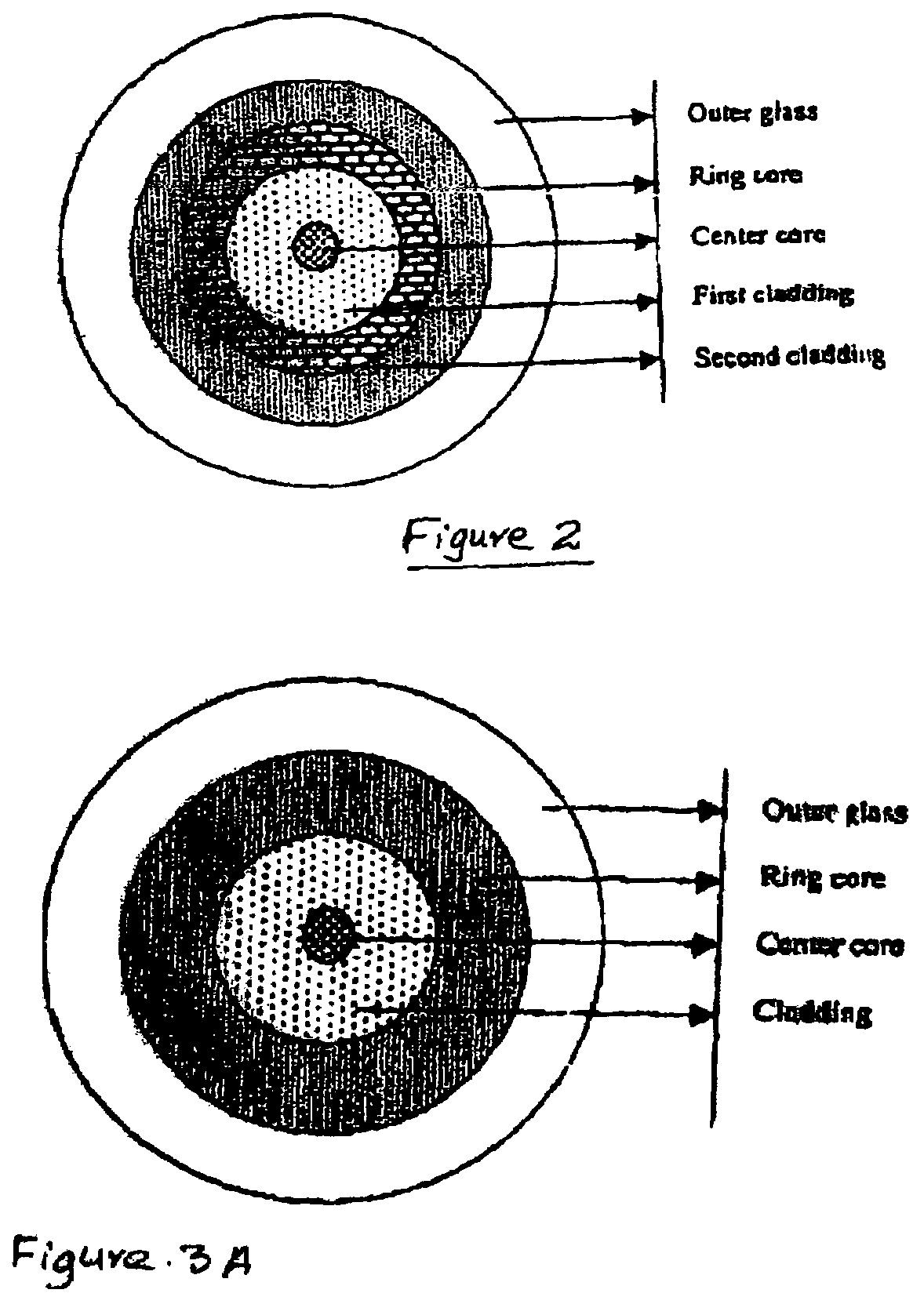
The configuration of this fiber is such that the refractive indices of centre core and the ring core are higher than that of the outer glass region and refractive indices of the claddings are lower than that of the outer glass region and the refractive indices are so selected that dispersion and chromatic dispersion slope are low and the bend loss is also low, but only during C- and L-band transmissions meaning thereby it is not suitable for S-band application.
The another limitation of this fiber is that it has non-zero dispersion only at 1550 nm and not at 1460 nm, and therefore, it does have non-linearity problem, and can be used for only one channel of transmission and not for more than one channel of transmissions in the S-band region.
The refractive indices of core, cladding and ring core regions of the fibers disclosed in this US application are so selected that the fibers thus obtained have low dispersion slope, low dispersion loss and the higher effective area, but only during C- and L-band transmissions meaning thereby the fibers of this US application also are not suitable for S-band application.
The another limitation of these fibers is also same as of above fiber of first prior art, that is, these have non-zero dispersion only at 1550 nm and not at 1460 nm, and therefore, these do have non-linearity problem, and can be used for only one channel of transmission and not for more than one channel of transmissions in the S-band region.

Method used


Image

  • Dispersion optimized optical fiber for wideband optical transmission
  • Dispersion optimized optical fiber for wideband optical transmission
  • Dispersion optimized optical fiber for wideband optical transmission

Examples


Embodiment Construction

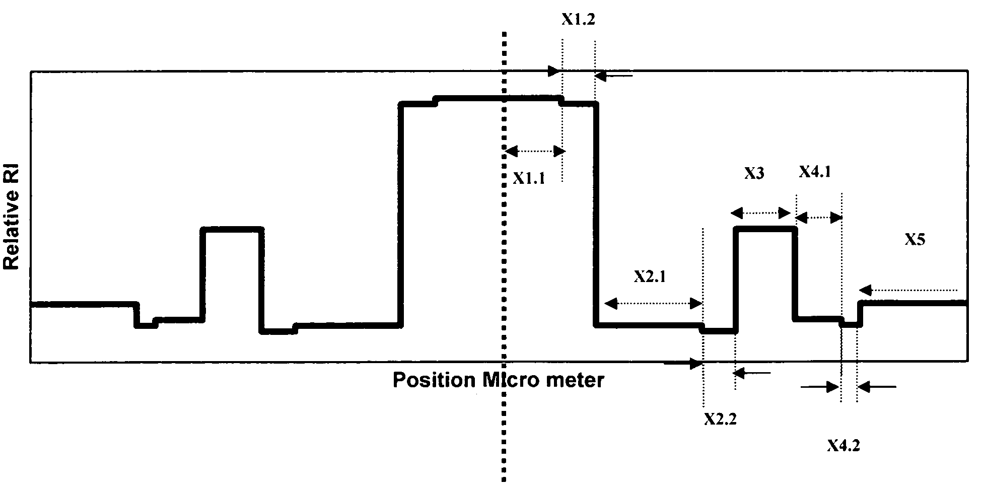
[0051]Now referring to accompanying FIG. 4, in accordance with the present invention a disclosed optical fiber, comprises a centre core 1, inner cladding 2, a ring core 3, outer cladding 4 and the outer glass region 5, characterized in that inner cladding 2 is provided onto the outer periphery of the centre core 1, and ring core 3 is provided onto outer periphery of the inner cladding 2 and the outer cladding 4 is provided onto outer periphery of the ring core 3, and the outer glass region 5 surrounds the outer cladding 4.

[0052]According to the present invention the refractive indices of various regions of the presently disclosed fiber are related in a manner that the centre core 1 and the ring core 3 have higher refractive indices than that of the outer glass region 5, and the inner cladding 2 surrounding the center core 1 and the outer cladding 4 surrounding the ring core 3 have lower refractive indices than that of the outer glass region 5.

[0053]In accordance with one embodiment ...


PUM


Abstract

A dispersion optimized optical fiber for wideband optical transmission is disclosed. The fiber comprise centre core, inner cladding, ring core, outer cladding and outer glass region, characterized by inner cladding provided onto outer periphery of the centre core, ring core, ring core provided onto outer periphery of inner cladding, outer cladding provided onto outer periphery of ring core, and outer glass region surrounding outer cladding, wherein refractive indices of various regions of the fiber are related in a manner that centre core has higher refractive index than that of ring core, ring core has higher refractive index than that of outer glass region, outer cladding has equal to or lower refractive index than that of outer glass region, and inner cladding has lower refractive index than that of outer cladding region, that is the refractive index of various regions of the fiber is related by relationship n1>n3>n5≧n4>n2 or the relationship Del1>Del3>Del5≧Del4>Del2.

Description

TECHNICAL FIELD OF THE INVENTION[0001]The present invention relates to dispersion optimized optical fiber for wideband transmission. Particularly, it relates to dispersion optimized optical fiber for wideband transmission having low dispersion, low dispersion slope, high effective area, reduced bending induced loss and low polarization mode dispersion [PMD]. More particularly it relates to dispersion optimized single mode optical fiber suitable for high speed wideband transmission in the wavelength region varying from about 1450 nm to about 1625 nm including wavelength region from about 1450 nm to about 1530 nm [S-band region], from about 1530 nm to about 1565 nm (C-band region) and from about 1565 nm to about 1625 nm (L-band region). Even more particularly it relates to dispersion optimized single mode fiber, which is suitable for transmission of higher bandwidth over longer distance with more uniform [low slope] chromatic dispersion over about 1450 nm to about 1625 nm windows and ...

Claims


Application Information

Patent Timeline
Patent Type & Authority Patents(United States)
IPC IPC(8): G02B6/036
CPCG02B6/02271G02B6/03644G02B6/03666G02B6/03688G02B6/02014G02B6/02242
Inventor PRASAD, SHASHIKANTNAIR, MANOL
Owner STERLITE TECHNOLOGIES
Learn More