Method for inverting near-surface velocity model by utilizing preliminary waveforms

A waveform inversion and velocity model technology, applied in seismic signal processing and other directions, can solve problems such as practical application limitations, limited data SNR inversion methods, multiple solutions and computational efficiency, and velocity model resolution limitations. The effect of reducing polysolution, improving stability and computational efficiency, and improving accuracy and stability

Inactive Publication Date: 2014-01-08
中国石油集团西北地质研究所有限公司
View PDF0 Cites 31 Cited by
  • Summary
  • Abstract
  • Description
  • Claims
  • Application Information

AI Technical Summary

Problems solved by technology

[0002] At present, the inversion of near-surface velocity models is mostly based on ray theory, using first-arrival travel time to invert near-surface velocity models, such as refraction static correction, tomographic inversion, etc. frequency approximation, only the low wavenumber components of the near-surface velocity model can be inverted (the model scale is much larger than the seismic wavelength), and the resolution of the inversion velocity model is limited
The full-waveform inversion method based on the wave theory utilizes the full-wave field information to invert the subsurface velocity model. Although the theory is relatively perfect, it is limited by the signal-to-noise ratio of the data, the multiple solutions of the inversion method itself, and the computational efficiency. , the practical application is very limited

Method used


Image

  • Method for inverting near-surface velocity model by utilizing preliminary waveforms
  • Method for inverting near-surface velocity model by utilizing preliminary waveforms
  • Method for inverting near-surface velocity model by utilizing preliminary waveforms

Examples


Embodiment Construction

[0035] Below in conjunction with accompanying drawing and example this technical scheme is further described

[0036] The near-surface velocity model method of first-arrival waveform inversion, this method includes two technologies: acoustic wave equation staggered grid finite-difference forward modeling and steepest descent method waveform inversion. The method steps of the implementation process are as follows:

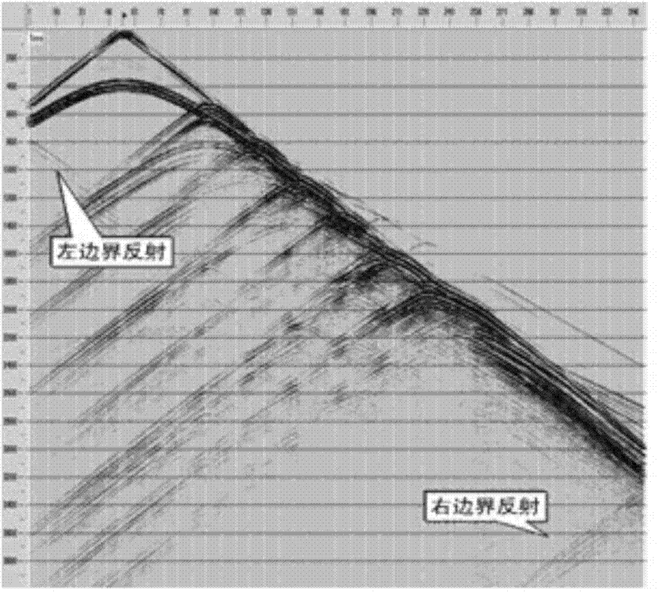
[0037] (1) Extract the time-domain first-arrival waveform record Pobs and initial velocity model;

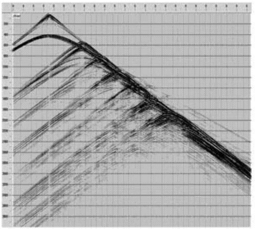
[0038] ⑵Using the staggered grid finite difference forward modeling of the acoustic wave equation to calculate the simulated wave field P cal , and calculate the wave field residual δp=P obs -P cal ;

[0039] (3) Back propagation of the wave field residual to obtain the return wave field P′;

[0040] (4) Calculate the gradient of the objective function by using the return wave field and the forward propagation wave field, that is, the update direction of the veloc...


PUM


Abstract

The invention discloses a method for inverting a near-surface velocity model by utilizing preliminary waveforms. The method comprises acoustic wave equation-based wave field forward modeling and steepest descent-based waveform inversion technologies, and comprises the following steps of 1, extracting time-domain preliminary waveform records and an initial model; 2, calculating a simulated wave field and a wave field residual by utilizing acoustic wave equation staggered grid finite-difference forward modeling simulation; 3, reversely propagating the wave field residual to obtain a retransmission wave field; 4, calculating a gradient of a target function by utilizing the retransmission wave field and a forward propagation wave field, and calculating an updating step length; 5, updating a speed model; 6, inspecting whether the speed model is consistent with an iteration stopping condition, outputting the speed model if the speed model is consistent with the iteration stopping condition, otherwise returning to the step 2, and continuing iterative updating. According to the method, a wave equation theory-based full-waveform inversion technology is used as reference, and preliminary waves with higher energy and more stable waveforms are used for inversion, so that the multiplicity of solutions of full-waveform inversion is reduced, and the inversion stability and the calculation efficiency are improved; the accuracy of static correction and shallow depth imaging is improved.

Description

technical field [0001] The invention belongs to the technical field of petroleum seismic exploration seismic data processing, and aims to improve the accuracy of the near-surface velocity model in seismic data processing, and further improve the accuracy of static correction and shallow depth imaging. Specifically, a method based on the first arrival waveform ( Different from the traditional first arrival travel time) inversion, it is a new technology and method to establish a high-precision near-surface velocity model. Background technique [0002] At present, the inversion of near-surface velocity models is mostly based on ray theory, using first-arrival travel time to invert near-surface velocity models, such as refraction static correction, tomographic inversion, etc. The frequency approximation can only invert the low wavenumber components of the near-surface velocity model (the model scale is much larger than the seismic wavelength), and the resolution of the inversion...

Claims


Application Information

Patent Timeline
Patent Type & Authority Applications(China)
IPC IPC(8): G01V1/28G01V1/36
Inventor 胡自多韩令贺王宇超王述江雍运动寇龙江
Owner 中国石油集团西北地质研究所有限公司
Why Eureka
Try Eureka