Feedback compensation detector for a direct conversion transmitter

a direct conversion transmitter and compensation detector technology, applied in the field of radio frequency (rf) signal transmission, can solve problems such as propagate signal impairmen

Active Publication Date: 2006-01-17
MALIKIE INNOVATIONS LTD
View PDF9 Cites 108 Cited by
  • Summary
  • Abstract
  • Description
  • Claims
  • Application Information

AI Technical Summary

Problems solved by technology

Such transmitter chains, however, typically propagate signal impairments which are often resultant f

Method used


Image

  • Feedback compensation detector for a direct conversion transmitter
  • Feedback compensation detector for a direct conversion transmitter
  • Feedback compensation detector for a direct conversion transmitter

Examples


Embodiment Construction

Impairment Compensation Feedback Path

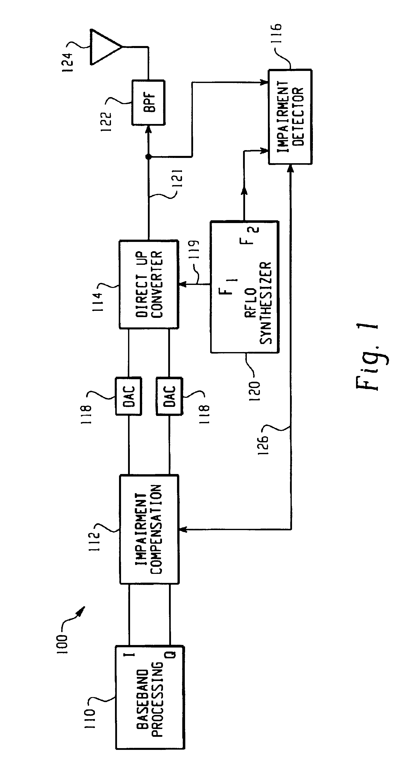
[0017]Referring now to the drawing figures, FIG. 1 is a block diagram of a direct up-conversion transmitter chain 100 with an impairment compensation feedback path. The transmitter chain 100 includes a baseband processor 110, an impairment compensator 112, a direct up-converter 114, and an impairment detector 116. The baseband processor 110 may, for example, be a digital signal processor (DSP), a central processing unit (CPU), or some other type of processing device or logic circuitry. The transmitter chain also includes a pair of digital-to-analog converters DACs 118, a frequency synthesizer 120, a band pass filter 122, and an antenna 124. Operationally, the impairment detector 116 measures signal impairments in the direct up-converter output 121, and generates a feedback signal 126 that is coupled to the impairment compensator 112. Exemplary signal impairments which may be detected by the impairment detector 116 are described below with referen...


PUM


Abstract

A feedback compensation detector for a direct conversion transmitter includes a baseband processor, a direct up-converter, an antenna, and an impairment detection and compensation feedback circuit. The baseband processor generates an in-phase (I) baseband signal and a quadrature-phase (Q) baseband signal. The direct up-converter is coupled to the baseband processor, and combines the I and Q baseband signals with an RF carrier signal to generate an RF output signal. The antenna is coupled to the direct up-converter, and transmits the RF output signal. The impairment detection and compensation feedback circuit is coupled to the RF output signal and the I and Q baseband signals. The impairment detection and compensation feedback circuit down-converts the RF output signal to generate an intermediate frequency (IF) signal, measures as least one signal impairment in the IF signal, and pre-distorts the I and Q baseband signals to compensate for the measured signal impairment.

Description

CROSS-REFERENCE TO RELATED APPLICATION[0001]This application claims priority from and is related to the following prior application: Feedback Compensation Detector For A Direct Conversion Transmitter And Method Of Operating Same, U.S. Provisional Application Ser. No. 60 / 291,239, filed May 15, 2001. This prior application, including the entire written description and drawing figures, is hereby incorporated into the present application by reference.FIELD OF THE INVENTION[0002]This application relates generally to the field of radio frequency (RF) signal transmission. More specifically, a feedback compensation detector for a direct conversion transmitter is provided that is particularly well-suited for use in a Quadrature Amplitude Modulated (QAM) transmitter, but may also provide utility in any transmitter that uses sufficiently independent modulation on the two quadrature axes (I and Q), such as a Code Division Multiple Access (CDMA) transmitter, a Wideband Direct Sequence CDMA (WCDM...

Claims


Application Information

Patent Timeline
IPC IPC(8): H04B1/02H04K1/02H03C3/40H04B1/04H04B1/30H04B1/62H04L27/34
CPCH03C3/40H04B1/30H04B1/0475
Inventor NIELSEN, JORGEN S.
Owner MALIKIE INNOVATIONS LTD
Why Eureka
Try Eureka