Method and apparatus for verifying the integrity and security of computer networks and implementing counter measures

a computer network and integrity verification technology, applied in the field of methods, can solve the problems of global security patchwork, intrusion detection and global security patchwork, and the topology of the interconnected network has grown increasingly complex, and achieve the effect of thwarting suspected intruder attacks on the target network and reducing the number of false alarms

Inactive Publication Date: 2006-01-17
SICORTEX
View PDF9 Cites 221 Cited by
  • Summary
  • Abstract
  • Description
  • Claims
  • Application Information

AI Technical Summary

Benefits of technology

[0015]It is another object of the present invention to provide a network security system which can analyze a steady stream of detected events and combine and prioritize them into a small number of security alerts.
[0031]In another example of the present invention, the subsystem, and the master system acting through the subsystem, can implement corrective measures to mitigate or thwart suspected intruder attacks on the target network.

Problems solved by technology

The topology of the interconnected networks has also grown increasingly complex, and often involves open networks such as the internet or the extranet that expose secure systems to increased threats of attack.
Consequently, no single solution has yet been proposed that addresses all current needs for intrusion detection, intrusion prevention and response.
This has resulted in a global security patchwork, inherently susceptible to attack and to individual systems which themselves implement a hodge podge of different security devices and techniques.
It is known, for example, that although a secure system connected to the internet may include firewalls and intrusion detection systems to prevent unauthorized access, weaknesses in individual security components are often sought out and successfully exploited.
The rapid introduction of new technology exacerbates the problem, creating or exposing additional weaknesses that may not become known even after a breach in security has already occurred.
A fundamental weakness shared in common by current intrusion detection and response systems is their “flat” or non-hierarchical implementation.
Consequently, if the IDS is not updated, is disabled, evaded or encounters an unknown or new method of attack, it will not respond properly.
However, if steps are not taken at this point in the attack to prevent further penetration into the target network, the intruder may actually begin to invade the network, exploiting any security weaknesses (such as the IDS that may have not reacted earlier to the intruder), and securing a foothold on the network.
It is typical, however, that successful attacks on network systems often begin by attacking the security subsystems in place on the target network that are responsible for detecting common intrusion signatures, disabling those systems and destroying evidence of the intrusion.
If not, they are considered compromised, and an attack may already be underway.
This method is an improvement over passive systems that do not check themselves and therefore cannot properly report on their own status when they have been disabled.
A major shortcoming of this approach is that these security systems reside on the same networks that they seek to protect and are similarly vulnerable to attack once an intruder has gotten a foothold on the network.
Additionally, by only testing security from a single location, they will likely not detect a ‘filtered’ detection system, whereby only specific events are not reported.
Further, with the ability of a single IDS sensor to create hundreds of thousands of events, many companies find it impossible to effectively monitor and prioritize the constant stream of alerts.
However, this often has an undesired effect: it diminishes the ability of an IDS to detect real threats, resulting in a high rate of false negatives.
However, they do a poor job of assessing the weakest link in security, i.e., a company's connection to the Internet.

Method used


Image

  • Method and apparatus for verifying the integrity and security of computer networks and implementing counter measures
  • Method and apparatus for verifying the integrity and security of computer networks and implementing counter measures
  • Method and apparatus for verifying the integrity and security of computer networks and implementing counter measures

Examples


Embodiment Construction

[0038]The preferred embodiments of a network security system according to the present invention will hereinafter be described with reference to the accompanying drawings.

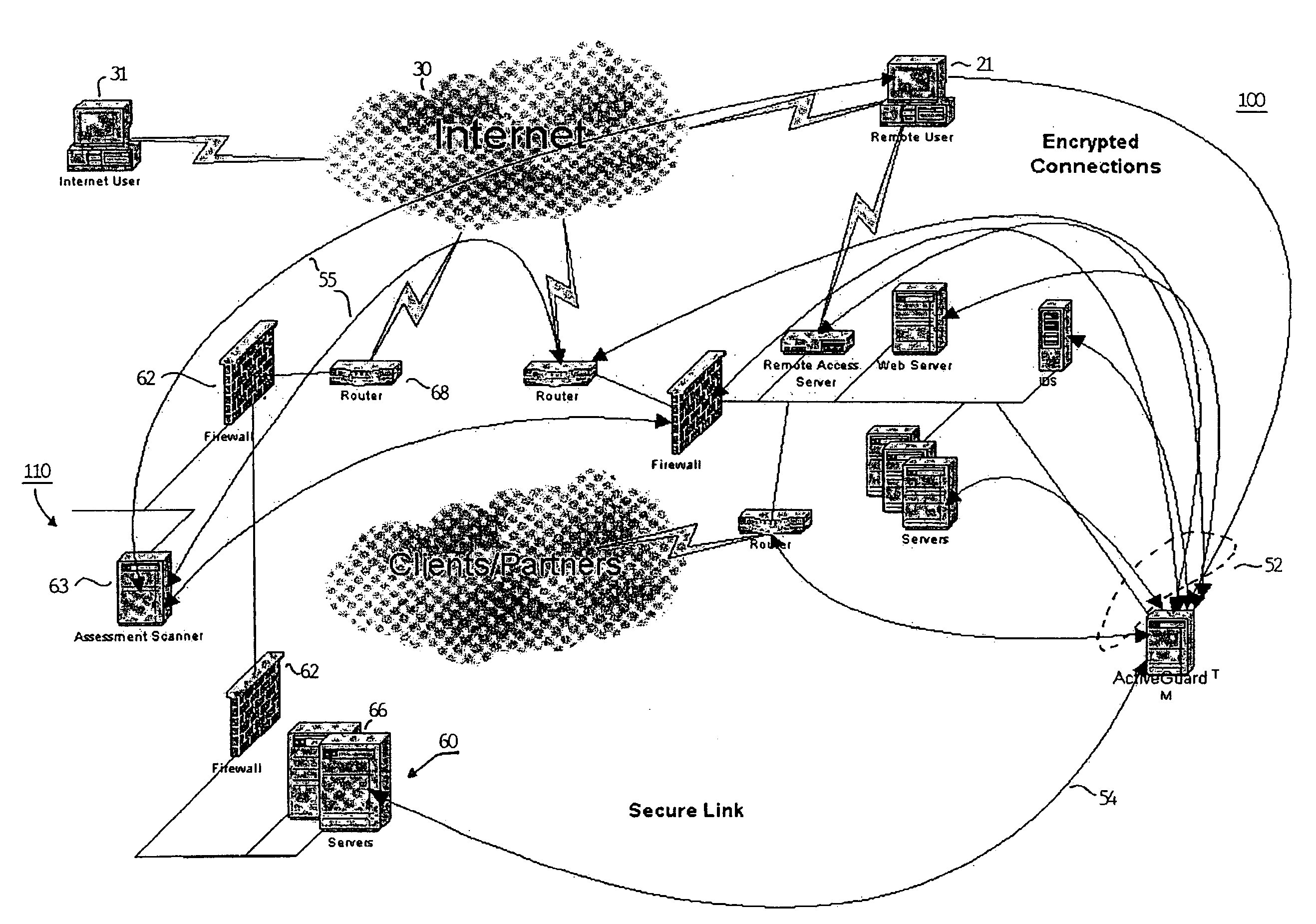
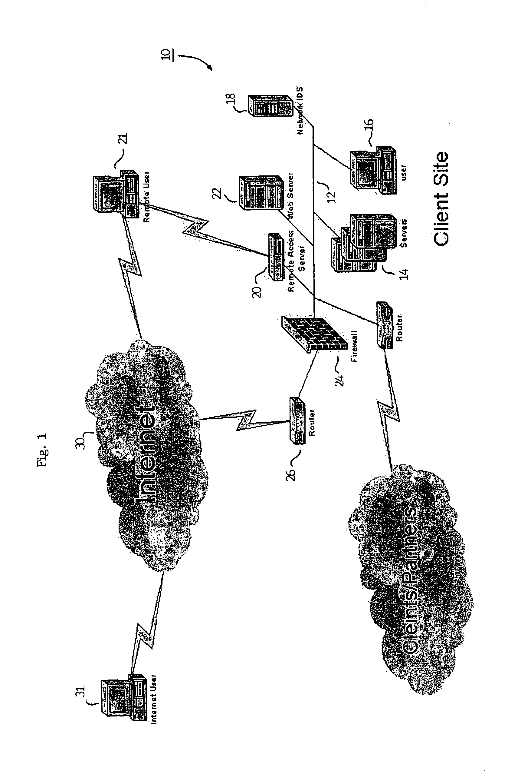
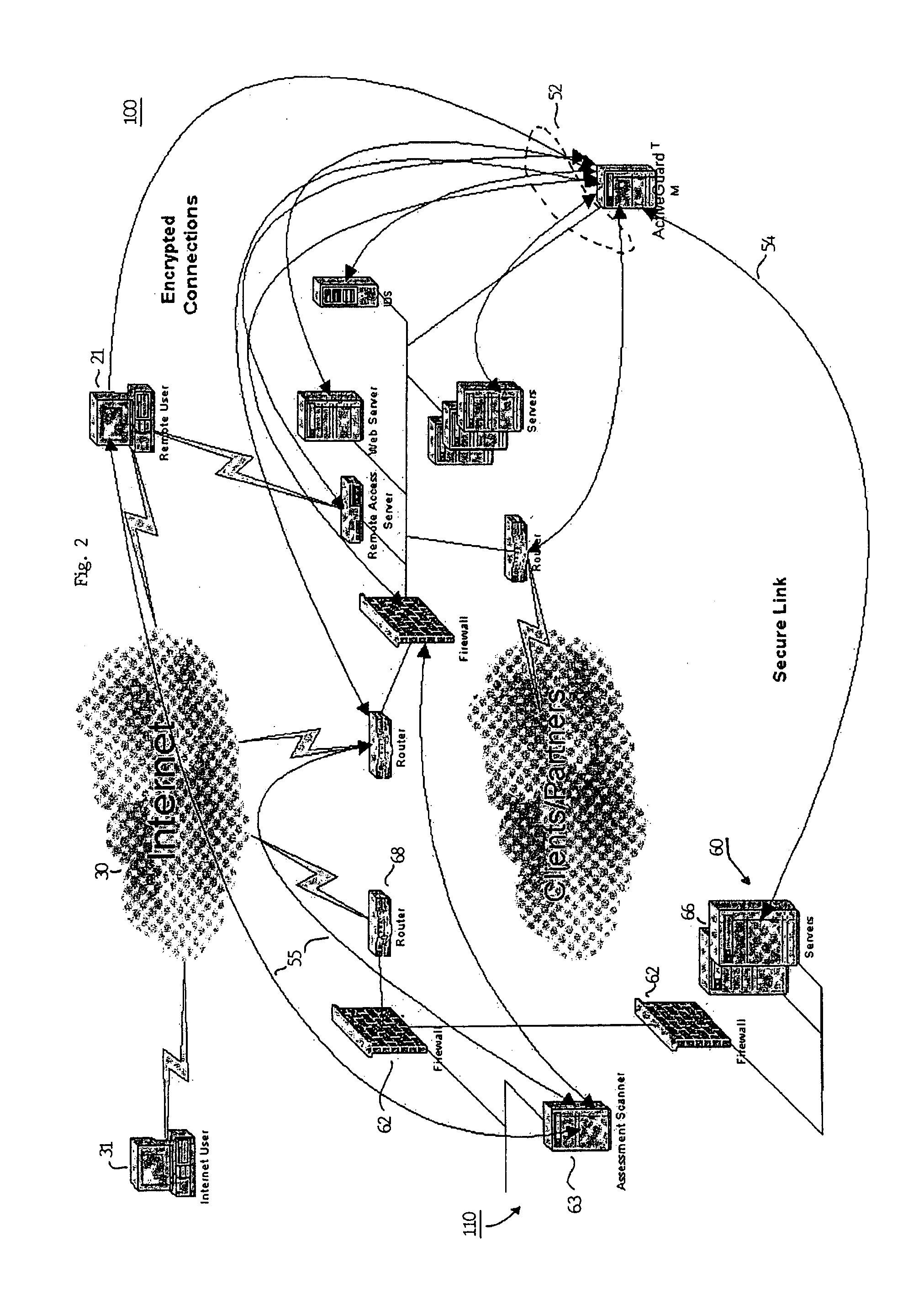
[0039]Referring to FIG. 2, a first embodiment of the present invention is shown. Target network 100 is shown having the same basic components as the network of the prior art shown in FIG. 1 with the addition of security subsystem 50, however, it should be noted that the actual configuration of the target network is not critical with the exception of at least one security subsystem 50. Each of the security subsystem 50, servers 14, workstations 16, IDS 18, remote access server 20, web server 22, firewall 24 and router 26 are connected together over network backbone 12. Each of the devices carry out communication over the backbone in accordance with a predetermined communication protocol such as Transmission Control Protocol / Internet Protocol (TCP / IP). Security subsystem 50, firewall 24, IDS 18, and all servers, route...


PUM


Abstract

A method and apparatus for verifying the integrity of devices on a target network. The apparatus has security subsystems and a master security system hierarchically connected to the security subsystems via a secure link. The target network includes various intrusion detection devices, which may be part of the security subsystem. Each intrusion detection device generates a plurality of event messages when an attack on the network is detected. The security subsystem collects these event messages, correlates, and analyzes them, and performs network scanning processes. If certain events warrant additional scrutiny, they are uploaded to the master security system for review.

Description

RELATED APPLICATIONS[0001]This application is a continuation-in-part of the U.S. patent application Ser. No. 09 / 770,525, filed Jan. 25, 2001 and claims all rights of priority thereto.FIELD OF THE INVENTION[0002]This invention relates to a method and apparatus for verifying the integrity of a computer security subsystem for preventing attacks on computer network security systems.BACKGROUND OF THE INVENTION[0003]Concurrent with the rise in connectivity among diverse computer networks and the corresponding increase in dependence on networked information systems, there has been a dramatic increase in the need for robust security to enforce restrictions on access to and prevent intrusion on secure systems. The topology of the interconnected networks has also grown increasingly complex, and often involves open networks such as the internet or the extranet that expose secure systems to increased threats of attack. Consequently, no single solution has yet been proposed that addresses all cu...

Claims


Application Information

Patent Timeline
Patent Type & Authority Patents(United States)
IPC IPC(8): G06F11/30G06F15/16G06F15/173G06F21/20G06F13/00H04L9/10H04L29/06
CPCH04L63/1433H04L63/1416H04L63/20
Inventor HRABIK, MICHAELGUILFOYLE, JEFFREYMAC BEAVER, EDWARD
Owner SICORTEX
Why Eureka
Try Eureka