
Method for detecting and evaluating the conditions of vehicle movement dynamics for a motor vehicle

a technology of vehicle movement and vehicle dynamics, applied in the field of electronic sensors, can solve problems such as discrepancies in determining the forces that act on wheels or tires, and achieve the effect of reducing the errors in the evaluation of wheel forces

Inactive Publication Date: 2006-01-24
CONTINENTAL TEVES AG & CO OHG
View PDF16 Cites 10 Cited by
  • Summary
  • Abstract
  • Description
  • Claims
  • Application Information

AI Technical Summary

Benefits of technology

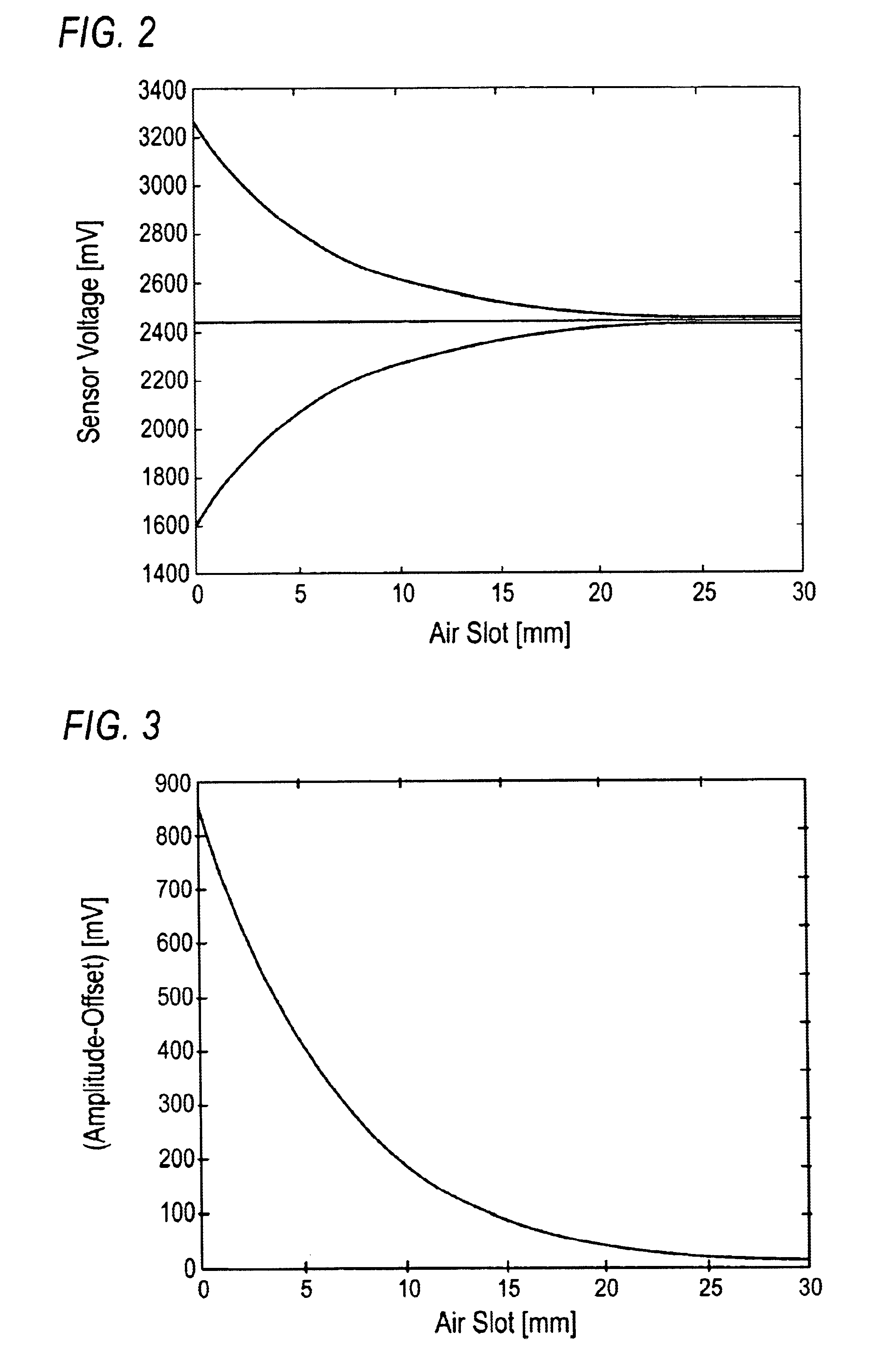
The present invention relates to a method and control circuit for reducing errors in evaluating wheel forces, especially deformations of the wheel rim and tire, in a motor vehicle by using tire sensors. The invention takes into account the preadjusted air slot between the rotating encoder and pick-up for measuring data, as a standard of the transverse forces acting on the wheel or tire. The method and control circuit standardize the output signal of the pick-up for measuring data to a standardized value, regardless of the preadjusted distance between the pick-up and encoder. This allows for error-minimized processing of the output signal without impairing its quality. The invention also allows for the use of different wheel rims with the same amount of rigidity and adjusts the output signal based on the vehicle-related distances between the pick-up and encoder. The invention reduces errors in evaluating wheel forces, especially deformations of the wheel rim and tire, in a motor vehicle.

Problems solved by technology

Tolerances which occur in the arrangement or manufacture of the pick-ups for measuring data, and / or different wheel rim systems, e.g. with different rim offsets, cause discrepancies in determining the forces that act on the wheels or tires.

Method used


Image

  • Method for detecting and evaluating the conditions of vehicle movement dynamics for a motor vehicle
  • Method for detecting and evaluating the conditions of vehicle movement dynamics for a motor vehicle
  • Method for detecting and evaluating the conditions of vehicle movement dynamics for a motor vehicle

Examples


Embodiment Construction

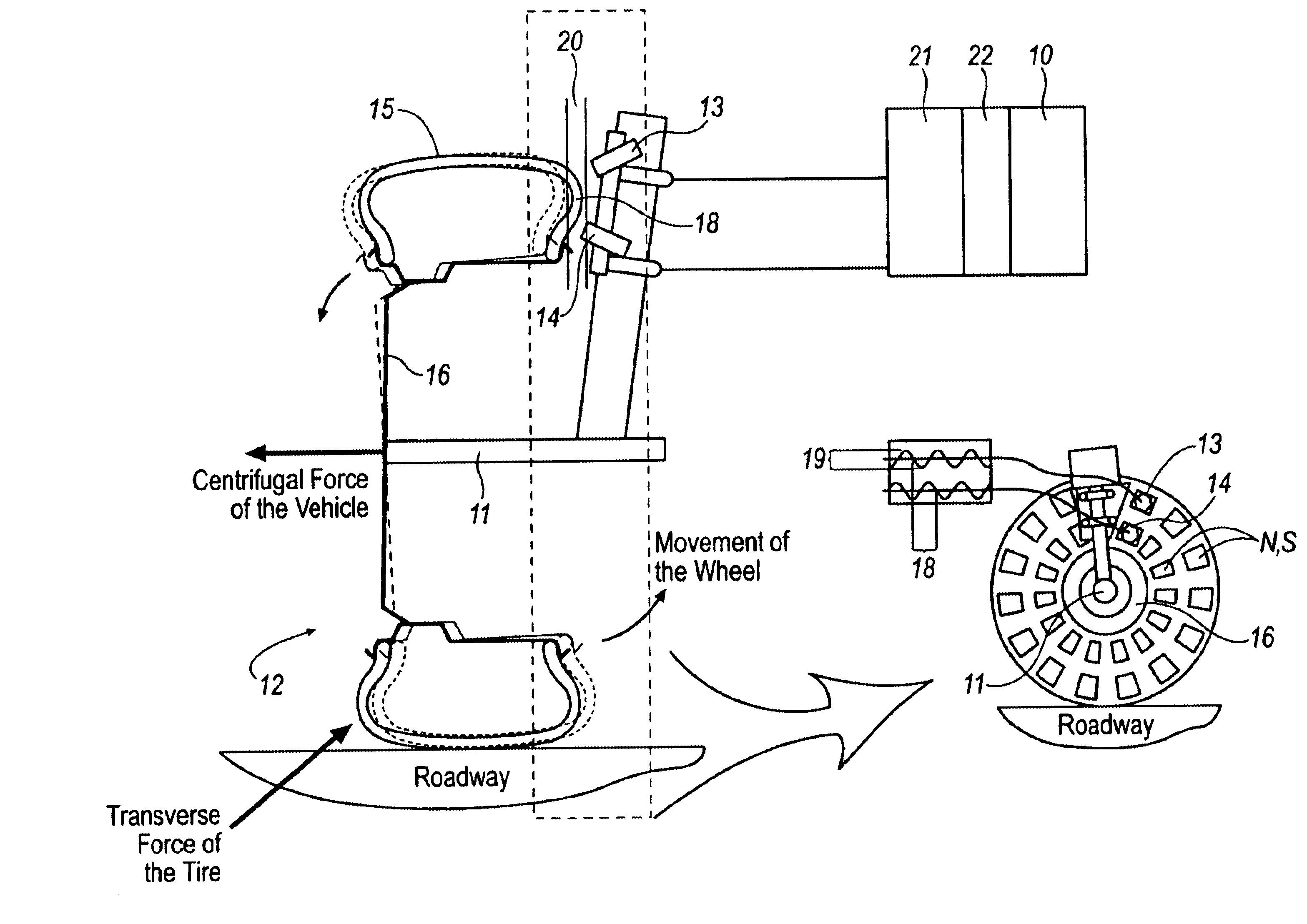
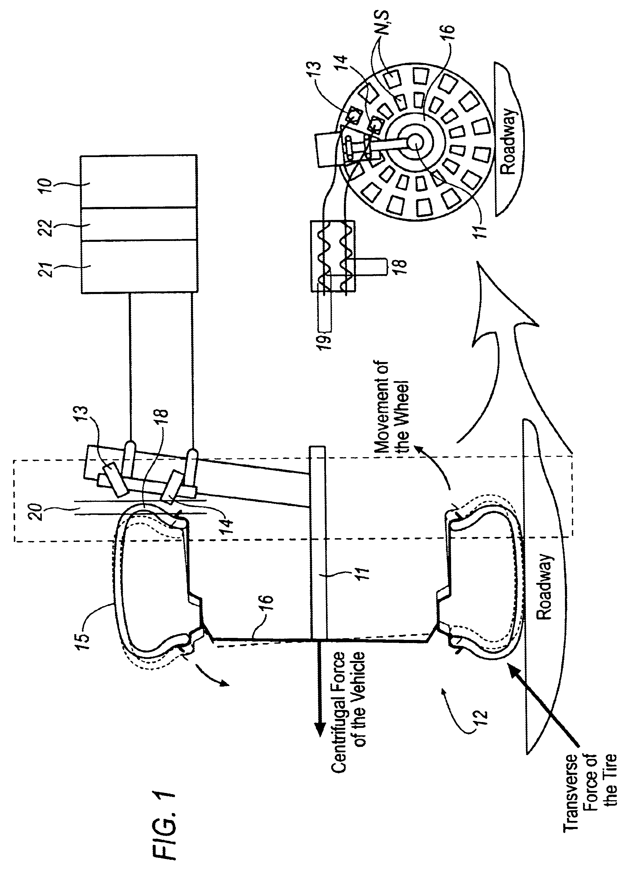
[0029]FIG. 1 shows a control circuit 10 which is connected to two magnetic-field-sensitive pick-ups for measuring data 13, 14 that are mounted on the chassis of a motor vehicle spaced radially from an axis of rotation 11 of wheel 12. The control circuit may be a component part of the pick-ups for measuring data or a separate unit or component of an ABS (anti-lock control system), TCS (traction slip control system), ESP (electronic driving stability control system), EHB (electrohydraulic brake control system), a vehicle suspension control system, and / or an EMB (electromechanic brake) control system. Vehicle tire 15 includes an encoder 17 with permanent-magnetic areas of alternating polarity N, S. The permanent-magnetic areas N, S are embedded in tire wall 17 of wheel 12.

[0030]A distance (air slot 20) is preadjusted between the encoder 18 and the pick-ups for measuring data 13, 14. When the wheel is deformed (=wheel rim 16 with tire 15 ) due to the longitudinal forces acting on the ti...


PUM

PropertyMeasurementUnit
timeaaaaaaaaaa
transverse forceaaaaaaaaaa
movement dynamicsaaaaaaaaaa

Abstract

The present invention relates to a method and a control circuit for detecting and evaluating the conditions of vehicle movement dynamics for a motor vehicle by means of wheel force sensors, preferably tire sensors, which take the preadjusted air slot between at least one rotating encoder and at least one pick-up for measuring data into account as a standard for the transverse forces that act on the wheel or on the tire. In order to reduce the errors in the evaluation of wheel forces, especially of deformations of the wheel rim and / or the tire detected by means of tire sensors, the air-slot-dependent operating point of the output signal of the pick-up for measuring data or a signal-conditioning device is set irrespective of the preadjustment of the said point which was made during predetermined driving behavior.

Description

[0001]This application is a 371 of PCT / EP00 / 08989 filed Sep. 9, 2000.TECHNICAL FIELD[0002]The present invention generally relates to electronic sensors and more particularly relates to a method and a control circuit for detecting and evaluating the conditions of vehicle movement dynamics for a motor vehicle by means of wheel force sensors, preferably tire sensors.BACKGROUND OF THE INVENTION[0003]Many methods for controlling the driving behavior of a vehicle are known in the art which use tire sensors for sensing the forces and moments that act on the tires. The term ‘tire sensor (SWT sensor)’ in this context refers to the encoder mounted in or on the tire and at least one pick-up for measuring data that is associated with the encoder and mounted on the chassis in a stationary manner. Whereas in EP 0 444 109 B1 the deformation of the tire profile area of the tire, i.e., the tire print, is monitored, WO 96 / 10505 proposes detecting the deformation of the side wall of a tire, i.e., tors...

Claims


Application Information

Patent Timeline
Patent Type & Authority Patents(United States)
IPC IPC(8): G01M19/00G01M99/00G01D3/02G01L5/20G01M17/06
CPCG01L5/20G01D3/021B60T2240/03
Inventor BLECKMANN, HANSGOSLAR, MARIUS
Owner CONTINENTAL TEVES AG & CO OHG
Learn More