Direction control device of control target

a control device and target technology, applied in the direction of non-deflectable wheel steering, battery/cell propulsion, transportation and packaging, etc., to achieve the effect of quick and accurate realization

Inactive Publication Date: 2006-01-24
PARKSIDE IP LLC
View PDF32 Cites 66 Cited by
  • Summary
  • Abstract
  • Description
  • Claims
  • Application Information

AI Technical Summary

Benefits of technology

[0007]An object of the present invention is to provide a direction control device which does not require a structure for steering the front wheels, which is capable of providing a rotation difference to the left and right drive wheels by the passenger merely changing the steering device such as a handle or lever in a desired direction, and, as a result, which enables the change in direction of the vehicle in a desired direction. Another object of the present invention is to provide control technology capable of quickly and accurately realizing the foregoing drive control of the left and right drive wheels. Still another object of the present invention is to provide a direction control device capable of applying a circular steering wheel as the steering device. A further object of the present invention is to provide, in an electric vehicle having front wheels as auxiliary wheels, control technology in which added to the foregoing direction control device is a control mechanism enabling the travel of an electric vehicle with such auxiliary wheels afloat while such electric vehicle is running. A still further object of the present invention is to provide an electric vehicle comprising the foregoing direction control device.
[0019]The PLL (Phase Locked Loop) circuit is a feedback control circuit for synchronizing the phases, and is used for controlling the output phase such that the signal having a frequency of a pulse or AC signal becomes the same phase as the reference signal. This technology is often used in spindle motors for rotating the hard disk of information processing equipment, motors for rotating the VCR heads, motors for rotating the polygon mirror for performing laser scans, and so on, and the target motor was in most cases a stepping motor or the like. With the present invention, the rotational speed of the motor can be controlled by performing inverter control even against AC motors and DC motors to be driven under a constant voltage, and, by further employing PLL technology, high-precision rotation angle control is enabled. Particularly, for example, in a case when the load against the movement of the driven plate alters, torque control becomes necessary. Nevertheless, by measuring the current speed of the driven plate, speed control is enabled in a state of adding the torque load.

Problems solved by technology

Moreover, with the vehicles employing the steering method of providing a rotation difference to the left and right rear wheels, there is an inconvenience in that the passenger is required to provide a suitable rotation difference to the left and right rear wheels each time he / she wishes to change the direction of the vehicle.

Method used


Image

  • Direction control device of control target
  • Direction control device of control target
  • Direction control device of control target

Examples


Embodiment Construction

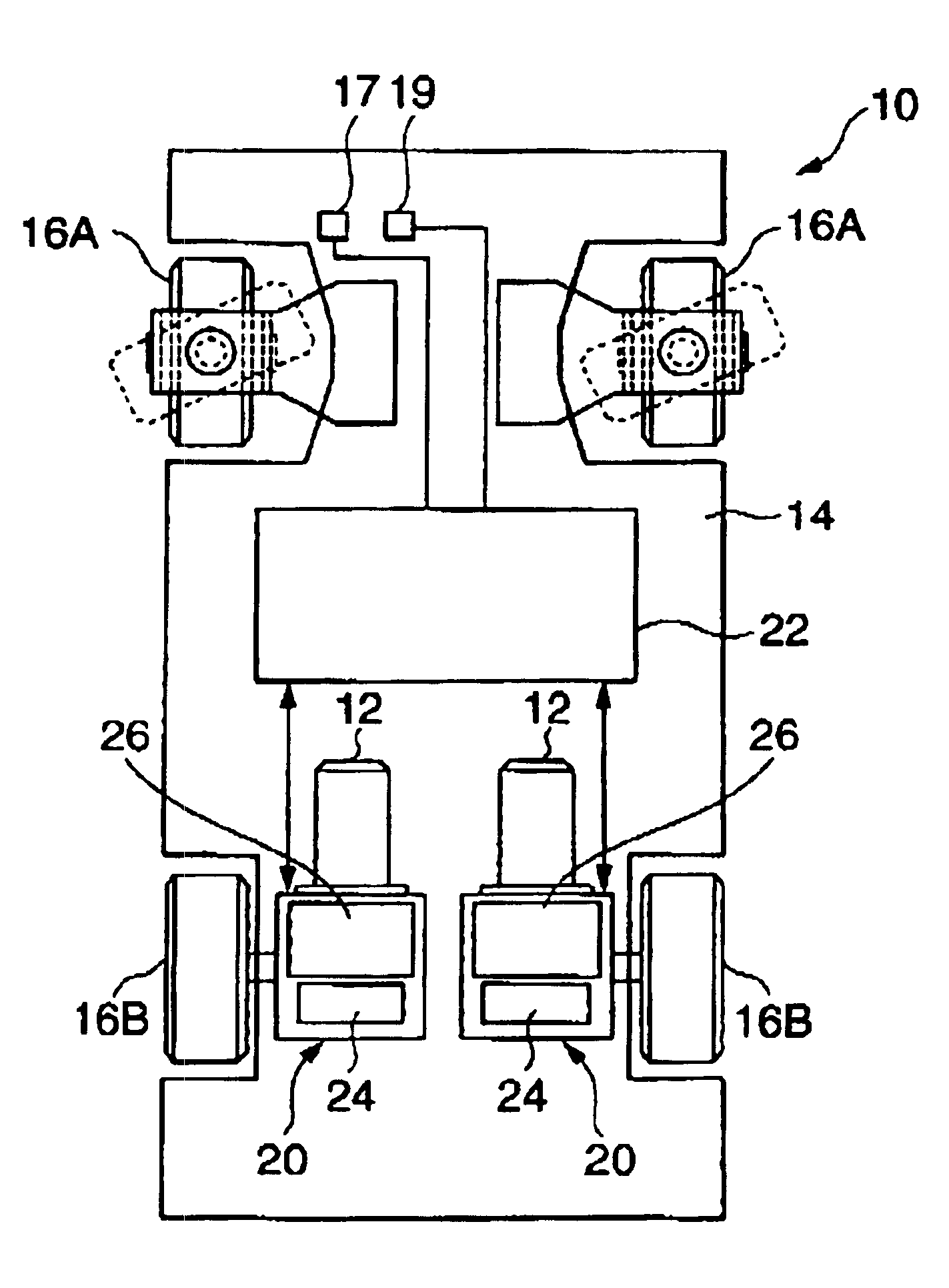
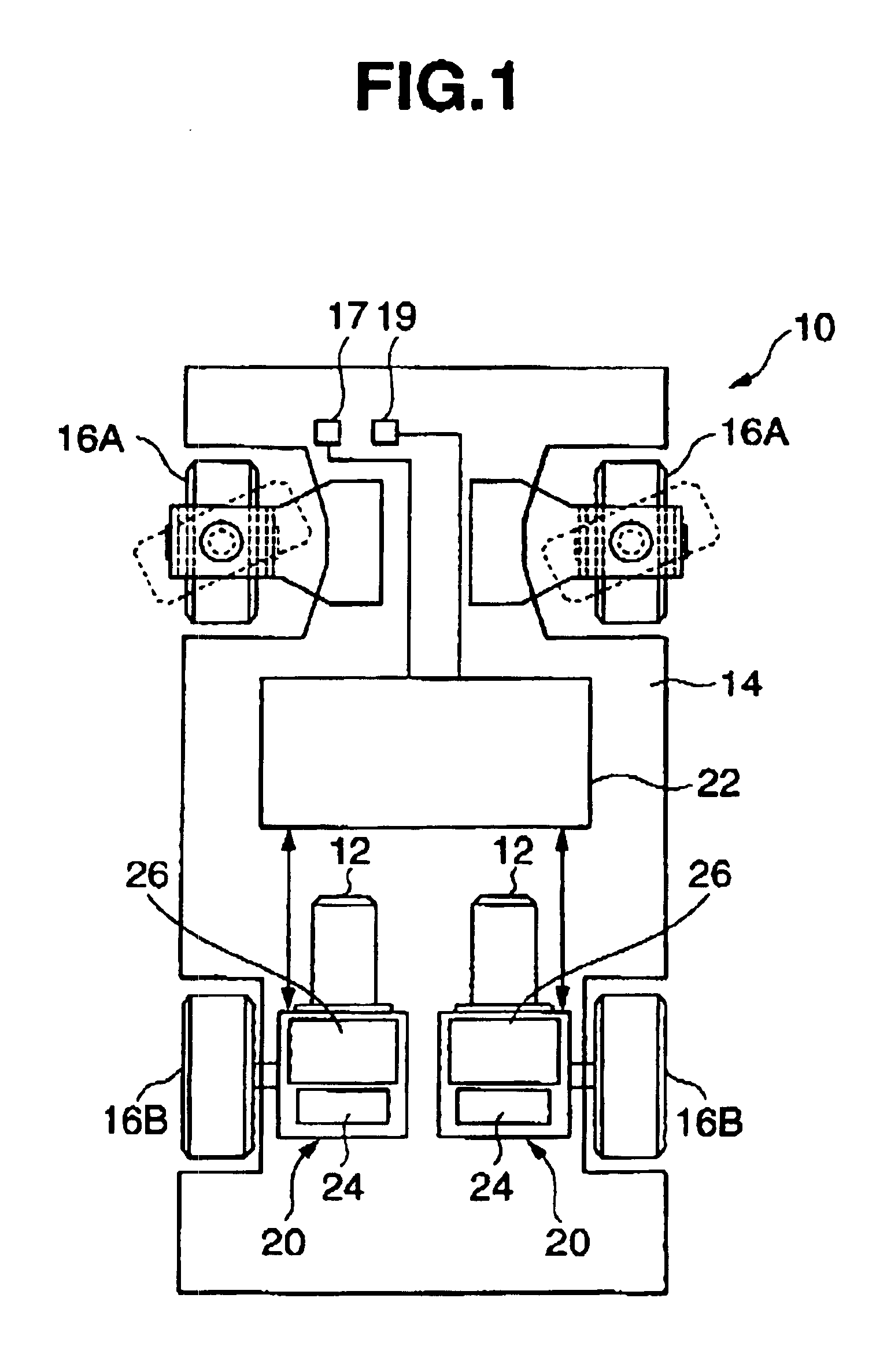
[0040]FIG. 1 shows the electric vehicle 10 comprising an example of the direction control device of the present invention. This vehicle 10 drives the respective left and right rear wheels 16B with an electric motor (pulse motor 12 described later). The vehicle body 14 is provided with two wheels in the front and back; that is, a total of four wheels. Reference numeral 16A shows the two front wheels and reference numeral 16B shows the two rear wheels. These four wheels 16 ground and support the vehicle 10 on the road surface.

[0041]The front wheels 16A are so-called cast type wheels in which the direction thereof freely changes in accordance with the traveling direction of the vehicle, and are non-drive wheels. These front wheels 16A are not steered with a steering device (steering wheel), and follow the moving direction and turning direction of the vehicle. The steering of the vehicle, as described later, is achieved by providing a rotation difference to the left and right rear wheel...


PUM


Abstract

The left and right rear drive wheels of a vehicle are controlled independently, and the traveling direction of the vehicle is changed by providing a rotational speed difference between each of the left and right rear drive wheel. A vehicle operator merely designates the turning direction by moving an operation stick, e.g., to the left or right, which will in turn enable an automatic turn at an optimum curvature to be performed which frees the vehicle operator from complicated steering operations. A highly precise and responsive turn is achieved when the left and right independent control is implemented with a PLL control circuit.

Description

BACKGROUND OF THE INVENTION[0001]1. Field of the Invention[0002]The present invention relates to a direction control device capable of altering the motion of the control target having a plurality of driving means by independently controlling the drive mechanism, and, for example, relates to a direction control device of an electric vehicle of a two-wheel drive and which is capable of changing directions based on the rotation difference of such drive wheels. As such drivers, for example, there are electric traveling vehicles such as an electric car, electric wheelchair, electric cart, and so on. The present invention may also be employed in electric construction machinery, electric welfare equipment, electric robots, electric toys, electric airplanes, and electric optical devices (camera, projector, etc.).[0003]2. Background Art[0004]In electric motor vehicles such as electric carts and electric cars, the vehicle speed is adjusted by controlling the rotational speed of the electric m...

Claims


Application Information

Patent Timeline
Patent Type & Authority Patents(United States)
IPC IPC(8): B62D11/02B60L11/18B60L15/20B62D11/04B62D11/18H02P29/00
CPCB60L11/1805B60L15/2036B62D11/183B62D11/04B60L2200/22Y02T10/7275Y02T10/7005Y10S388/911B60L50/52Y02T10/64Y02T10/70Y02T10/72
Inventor TAKEUCHI, KESATOSHI
Owner PARKSIDE IP LLC
Why Eureka
Try Eureka