Computer component rack mounting arrangement

a technology for computer components and racks, applied in the field of computer systems, can solve the problems of loss of the entire volume above the sliding rail structure on either side of the enclosure, and the support structure still does not provide adequate access to the lower regions of the enclosure, so as to reduce the profile of components, reduce the height profile of the sliding rail structure, and reduce the height profile

Inactive Publication Date: 2006-01-24
HEWLETT-PACKARD ENTERPRISE DEV LP
View PDF91 Cites 103 Cited by
  • Summary
  • Abstract
  • Description
  • Claims
  • Application Information

AI Technical Summary

Benefits of technology

[0008]The present invention provides a novel sliding rail mounting arrangement for a computer component rack designed to respond to these needs. The technique makes use of symmetrical components which can be mounted on either side of a support rack, and which significantly reduces the profile of components mounted directly adjacent to the component enclosure. The structure offers similar mechanical load-bearing capabilities to those of conventional structures, and may be configured to interface with racks of conventional design. By virtue of the reduced height profile of the sliding rail structure, volumes on either side of the component enclosure may be recaptured within the internal volume of the enclosure, for use in mounting internal circuitry and elements of the system. Similarly, the reduced height profile of the sliding rail components of the system permit greater access to the interior volume of the enclosures when the components are retracted from the cabinet for servicing.
[0009]Thus, in accordance with one aspect of the invention, a rack mounting system is provided for retractably supporting a computer system component in a computer rack. The system includes identical left and right support rails each being securable in the rack in mutually facing parallel relation. Each support rail includes first and second securement regions adjacent to longitudinal edges. The regions are symmetrical about the longitudinal axis of the support rail. The system also includes identical left and right slide assemblies secured to support regions of the support rails. The support rails may be recessed into the rack to provide additional space within the rack for the computer component. The slide assemblies are preferably substantially smaller in profile than the support rails, thus further reducing the space requirements of the system within the volume occupied by the component.

Problems solved by technology

While sliding rail mounting structure of the type described above are generally quite effective at adequately supporting servers and other computer components, they were not without drawbacks.
While some degree of access may be provided by securing the sliding rail component of the structure adjacent to the bottom of the enclosure, allowing the top of the enclosure to be removed, conventional sliding support structures nevertheless do not provide adequate access to lower regions of the enclosure owing to the height of the sliding rail.
Conventional enclosures typically include flat vertical side panels which are secured to the sliding rail structures, resulting in loss of the entire volume above the sliding rail structures on either side of the enclosure.

Method used


Image

  • Computer component rack mounting arrangement
  • Computer component rack mounting arrangement
  • Computer component rack mounting arrangement

Examples


Embodiment Construction

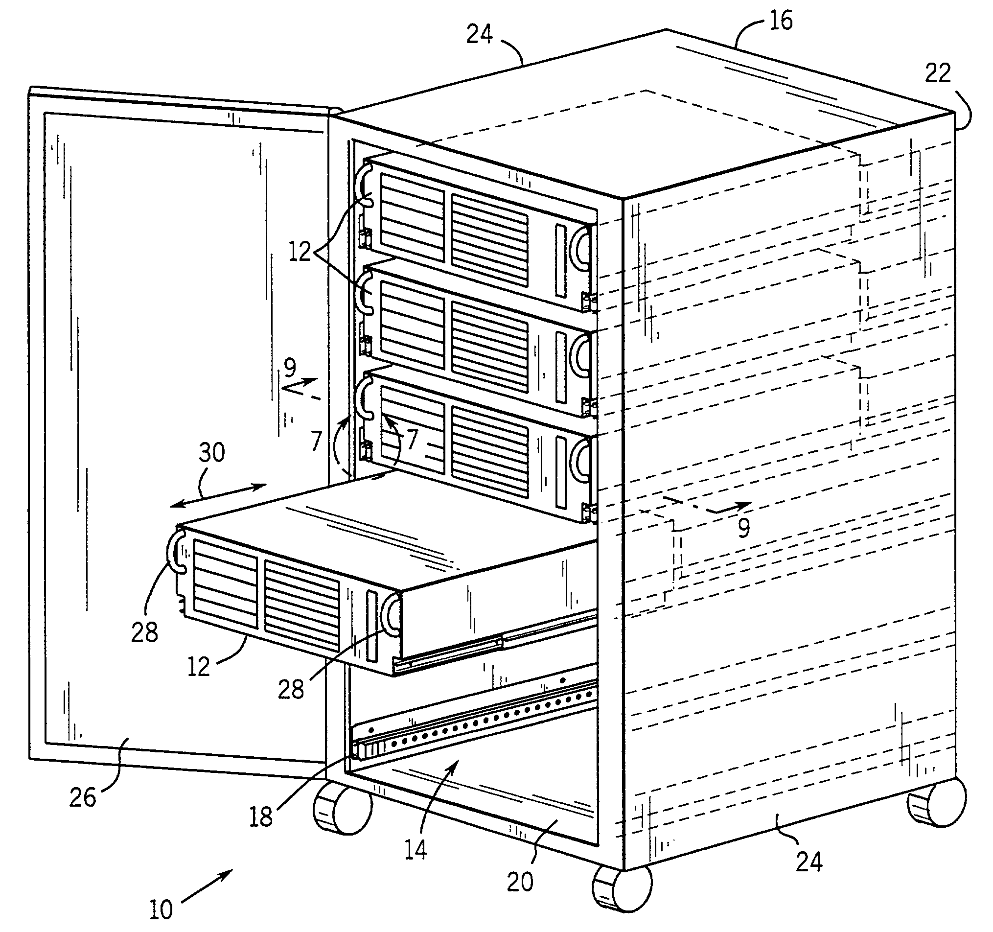
[0022]Turning now to the drawings, and referring first to FIG. 1, a rack-mounted computer system is illustrated generally and designated by the reference numeral 10. System 10 includes a plurality of components or servers 12, such as an individual server, supported in a vertical mounting rack 14. In the illustrated embodiment, rack 14 is constructed within a storage cabinet 16. Rack 14 includes a rail system, designated generally by the reference numeral 18, for supporting each individual server and for permitting the server to be recessed or inserted into the rack, or drawn from the rack for servicing, while remaining mechanically supported by cantilevered sliding rail arrangements as described more fully below.

[0023]Rack 14 and cabinet 16 include a front access opening 20 through which the servers may be retracted and reinserted, and a rear access opening 22 through which necessary connections may be made to each individual server for coupling the server to external components or ...


PUM


Abstract

A rail mounting arrangement for supporting a computer component, such as a server, in a rack includes a pair of support rails and slide rail assemblies supported by the support rail. The support rails are identical and include a pair of mounting regions on either side of a longitudinal axis. The slide rail assemblies have a lower profile than the support rails and may be mounted on either of the mounting regions. The slide rail assemblies are secured to the server and present a low profile, permitting greater access to internal components within the server housing for servicing. The support rails are recessed in the rack to reduce the space occupied by the rail system in the region of the rack in which the server is supported.

Description

BACKGROUND OF THE INVENTION[0001]1. Field of the Invention[0002]The present invention relates generally to the field of computer systems, such as servers, housed in a rack-mounted support structure. More particularly, the invention relates to a novel sliding rail support structure designed to provide increased internal volume in computer component enclosures in a low-profile rail arrangement.[0003]2. Description of the Related Art[0004]A variety of mechanical mounting structures have been devised for computer systems. In one type of computer system, typically referred to as server systems, a number of sub-components or servers are arranged in a central cabinet. The server enclosures are typically mounted in the cabinet in stacked vertical arrangements, with each server enclosure being secured within the cabinet by a sliding rail structure. The sliding rail structures permit the servers to be extracted and reinserted easily into the cabinet, such as for servicing of internal componen...

Claims


Application Information

Patent Timeline
Patent Type & Authority Patents(United States)
IPC IPC(8): A47F7/00A47B88/04A47B88/493G06F1/16H05K7/14
CPCA47B88/044H05K7/1489G06F1/16A47B88/10A47B88/43A47B88/493
Inventor VARGHESE, PAILY T.HASTINGS, ROBERT J.WESTPHALL, PAUL E.
Owner HEWLETT-PACKARD ENTERPRISE DEV LP
Why Eureka
Try Eureka