
Dynamic dorsal-blocking adjustable splint

a phalanx and adjustable technology, applied in the field of phalanx splint, can solve the problems of inability to effectively maintain foster various medical side effects, and always introduce the possibility of infection, and achieve the effect of convenient comfort, stable position and effective maintenance of the user's fractured phalangeal joints

Inactive Publication Date: 2006-01-24
SANTAANA DELA ROSA HORACIO
View PDF28 Cites 8 Cited by
  • Summary
  • Abstract
  • Description
  • Claims
  • Application Information

AI Technical Summary

Benefits of technology

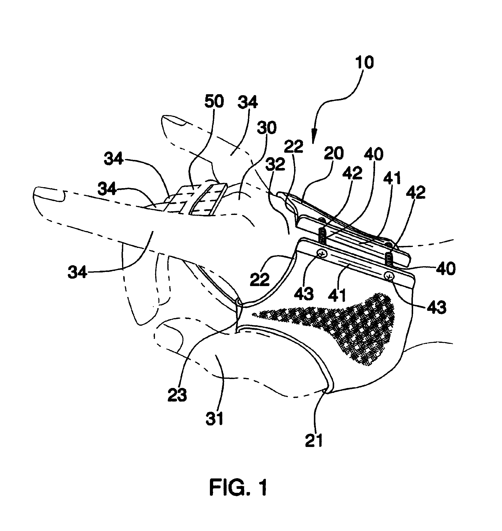
[0013]The present invention further includes a mechanism for adjustably maintaining the end portions at selected spatial relationships so that a user can advantageously readily apply and remove the splint as needed. The maintaining mechanism preferably includes a pair of rigid support members integrally disposed along the body end portions respectively and situated substantially parallel to the axis. Such support members are provided with a plurality of spaced apertures aligned along a length thereof respectively. A plurality of fastening members are threadably insertable through associated pairs of the support member apertures so that the body can be securely retrofitted about the user's hand.
[0015]Such a plate engages fractured metacarpals along a path substantially transverse to the axis so that associated metacarpal phalangeal joints will be effectively maintained at approximately 90 degrees offset counterclockwise from the axis. This conveniently allows medial and distal metacarpal phalangeal joints to move along unrestricted paths respectively. The plate preferably further includes a bottom layer formed from resilient foam material and extending along a length thereof. Such a bottom layer is positionable against the user's fractured phalangeal joints for conveniently providing comfort thereto when the splint is worn during extended periods of use.
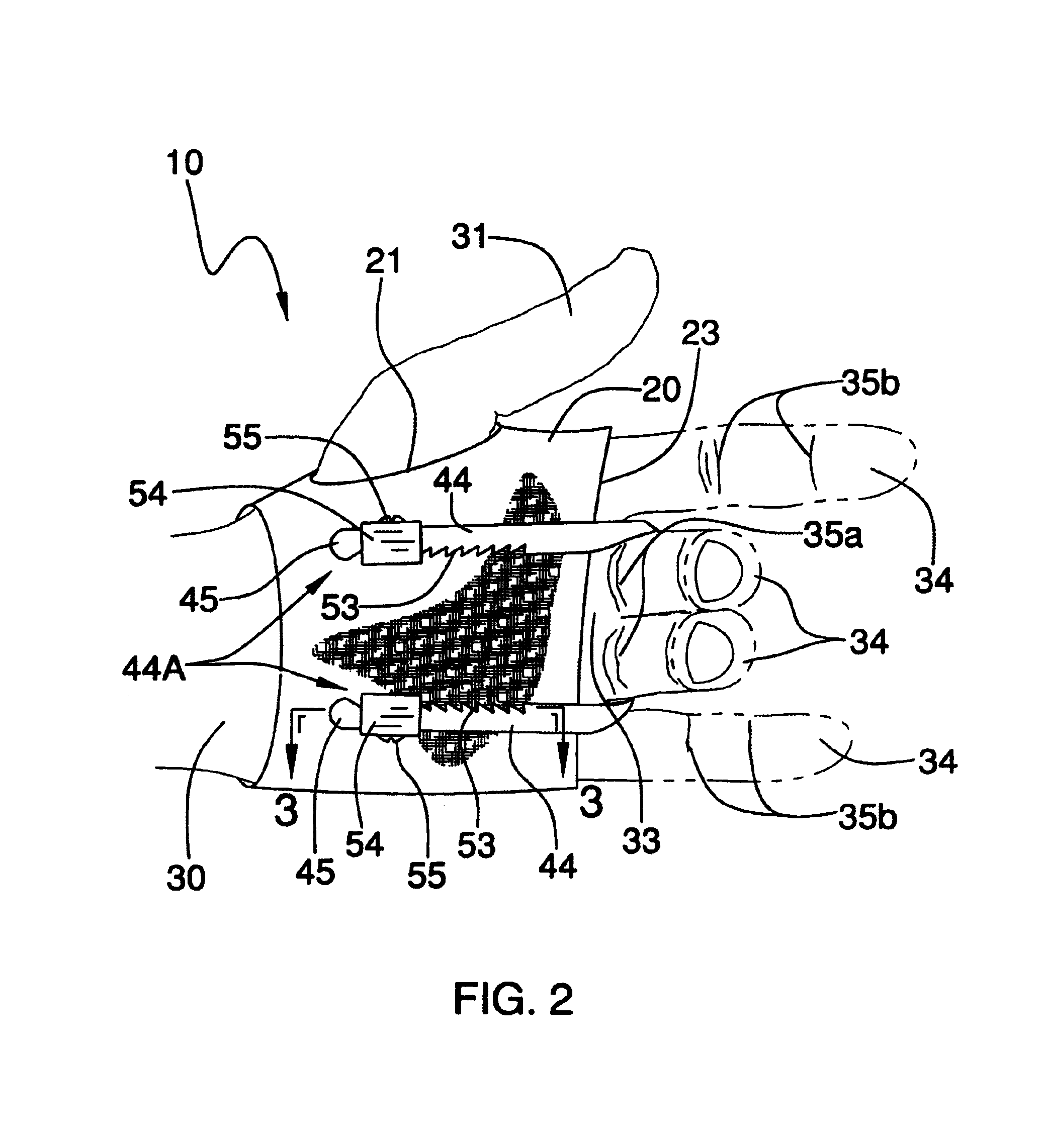
[0016]The splint further includes a mechanism for adjusting a length of the plate so the fractured metacarpals can be adapted between mobile and immobile positions. The clamp end portions preferably have serrated edges extending obliquely therefrom and situated medially towards a center of the user's palm. The adjusting mechanism includes a plurality of brackets secured to a proximal end portion of the body and adjacent to the user's palm. A plurality of fastening members are threadably engageable through the brackets for effectively assisting to maintain the clamp end portions at a substantially stable position.
[0017]Such brackets are oppositely spaced apart from the axis and include a plurality of rectilinear passageways provided with associated finger portions for locking and engaging the serrated edges respectively. The finger portions are integral with the brackets for advantageously limiting movement of the clamp end portions along a predetermined direction and cooperating with the brackets to effectively maintain the user's fractured phalangeal joints at the selected angle during operating conditions.
[0018]The splint may further include a plurality of pin members pivotally connected to the brackets and the body respectively so that the clamp can be selectively pivoted along straight paths and advantageously provide tolerable movement of the user's fractured phalangeal joint.

Problems solved by technology

However, each of these approaches is inherently flawed in that each fosters various medical side effects that may necessitate further medical treatment.
In addition, surgery always introduces the possibility of infection.
First, immobilization of the fracture in a properly reduced position also inconveniently immobilizes the patient's hand.
Secondly, immobilizing the finger in the crooked position pulls the extensor tendon onto the healing fracture.
This may cause the callus formed during healing to adhere to the extensor tendon.
Therefore, once the splint is removed, it is sometimes necessary to surgically release the tendon from the newly formed bone.

Method used


Image

  • Dynamic dorsal-blocking adjustable splint
  • Dynamic dorsal-blocking adjustable splint
  • Dynamic dorsal-blocking adjustable splint

Examples


Embodiment Construction

[0027]The present invention will now be described more fully hereinafter with reference to the accompanying drawings, in which a preferred embodiment of the invention is shown. This invention may, however, be embodied in many different forms and should not be construed as limited to the embodiment set forth herein. Rather, this embodiment is provided so that this application will be thorough and complete, and will fully convey the true scope of the invention to those skilled in the art. Like numbers refer to like elements throughout the figures.

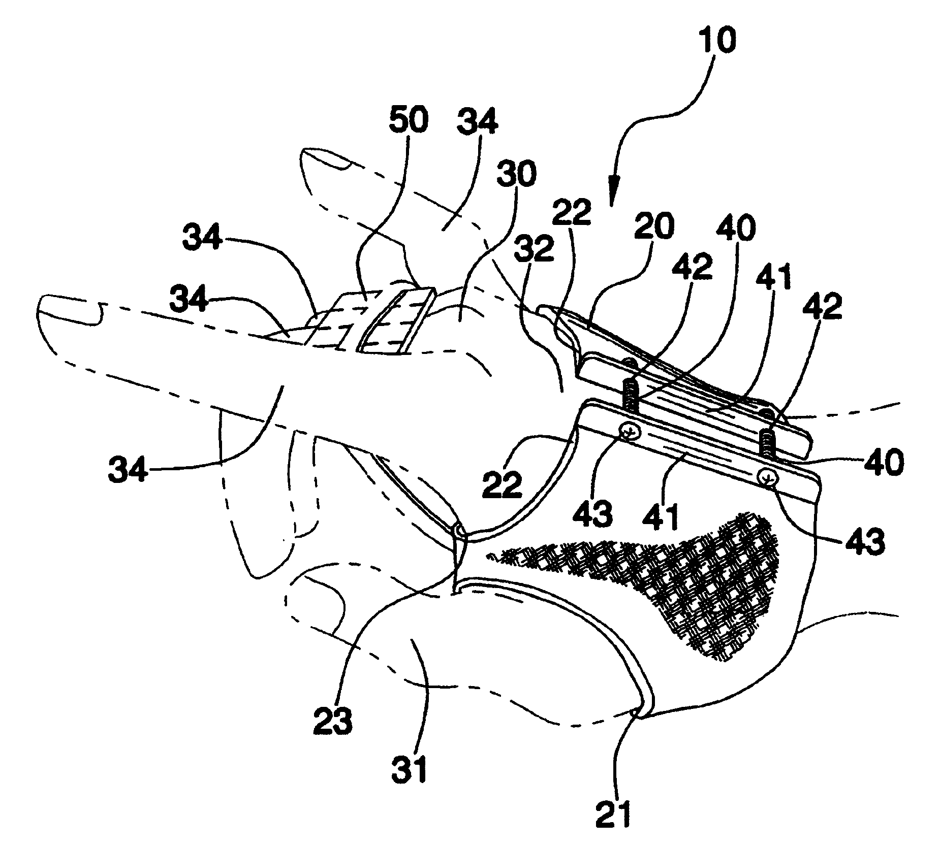
[0028]The apparatus of this invention is referred to generally in FIGS. 1–6 by the reference numeral 10 and is intended to provide an adjustable phalanx splint. It should be understood that the apparatus 10 may be used to splint various combinations of one to four metacarpals and should not be limited to splinting only one metacarpal.

[0029]Referring initially to FIG. 1, the apparatus 10 includes a flexible body 20 formed from durable material...


PUM


Abstract

A splint positionable about a user's hand for treating phalanx fractures includes a flexible body having a first opening for receiving a thumb therethrough and a second opening for allowing selected metacarpals to extend distally therethrough. The present invention further includes a mechanism for maintaining the end portions at selected spatial relationships and a flexible aluminum plate for engaging fractured metacarpals while allowing medial and distal metacarpal phalangeal joints to move along unrestricted paths respectively. The splint further includes a mechanism for adjusting a length of the plate so that the fractured metacarpals can be adapted between mobile and immobile positions.

Description

CROSS REFERENCE TO RELATED APPLICATIONS[0001]Not Applicable.STATEMENT REGARDING FEDERALLY SPONSORED RESEARCH OR DEVELOPMENT[0002]Not Applicable.REFERENCE TO A MICROFICHE APPENDIX[0003]Not Applicable.BACKGROUND OF THE INVENTION[0004]1. Technical Field[0005]This invention relates to a phalanx splint and, more particularly, to an adjustable phalanx splint for treating phalanx fractures.[0006]2. Prior Art[0007]Fractures of a finger's middle or proximal phalanx have traditionally been immobilized in a reduced position in one of two ways. One approach is surgical in nature and involves the insertion of pins or screws to stabilize or reduce the fracture. A second, non-surgical approach, involves casting the hand, wrist and distal forearm in cooperation with an outrigger splint to hold the fractured finger. However, each of these approaches is inherently flawed in that each fosters various medical side effects that may necessitate further medical treatment.[0008]For example, the surgical ap...

Claims


Application Information

Patent Timeline
IPC IPC(8): A61F5/00
CPCA61F5/05875
Inventor SANTAANA-DELA ROSA, HORACIO
Owner SANTAANA DELA ROSA HORACIO
Learn More