Nonwoven neutral line dryer fabric

a dryer fabric and neutral line technology, applied in the field of papermaking arts, can solve the problems of reducing machine efficiency, reducing paper product quality, and high cost, and achieve the effect of reducing the stretching of the supported paper sheet and reducing the stretching of the paper sh

Inactive Publication Date: 2006-01-24
ALBANY INT CORP
View PDF25 Cites 30 Cited by
  • Summary
  • Abstract
  • Description
  • Claims
  • Application Information

AI Technical Summary

Benefits of technology

[0021]The present invention is a nonwoven papermaker's fabric for use in a dryer section of a papermaking machine. The fabric has a spiral wound machine direction (MD) layer made of a first raw stock material. The spiral wound MD layer is formed by winding MD elements of the first raw stock material around a pair of parallel rolls or cylinders until the layer has a desired length and a desired width. A cross-machine direction (CD) layer of CD elements of a second raw stock material is overlaid and mated with the spiral wound MD layer. Preferably this is done so that the fabric has a neutral line oriented towards a paper side of the fabric. This neutral line placement in the z-direction or thickness direction in the fabric reduces stretching of the supported paper sheet when used in a papermaking machine as the fabric turns around the cylinders in the papermaking machine.
[0022]In another embodiment of the invention, the fabric has a first spiral wound machine direction (MD) layer of a first raw stock material. The first spiral wound MD layer is formed by winding MD elements of the first raw stock material in a first direction around a pair of parallel rolls or cylinders until the layer has a desired length and a desired width. A second spiral wound MD layer of a second raw stock material is formed by winding MD elements of the second raw stock material in a second direction, opposite to the first direction. The second spiral wound MD layer is overlaid and mated with the first spiral wound MD layer. Preferably this is done so that the fabric has a neutral line oriented towards a paper side of the fabric. This, as above, also reduces stretching of the paper sheet when used in a papermaking machine as the fabric turns around the cylinders in the papermaking machine.
[0025]The CD elements may be provided with MD oriented channels or grooves to provide for enhanced air handling by the fabric. The CD elements may also be wound.

Problems solved by technology

Drop off can reduce the quality of the paper product being manufactured by causing edge cracks.
Drop off can also reduce machine efficiency if it leads to sheet breaks.
Both of these expedients allow the air otherwise trapped in the compression wedge to be removed without passing through the dryer fabric, although both approaches are expensive.
These fabrics wear out and require replacement.

Method used


Image

  • Nonwoven neutral line dryer fabric
  • Nonwoven neutral line dryer fabric
  • Nonwoven neutral line dryer fabric

Examples


Embodiment Construction

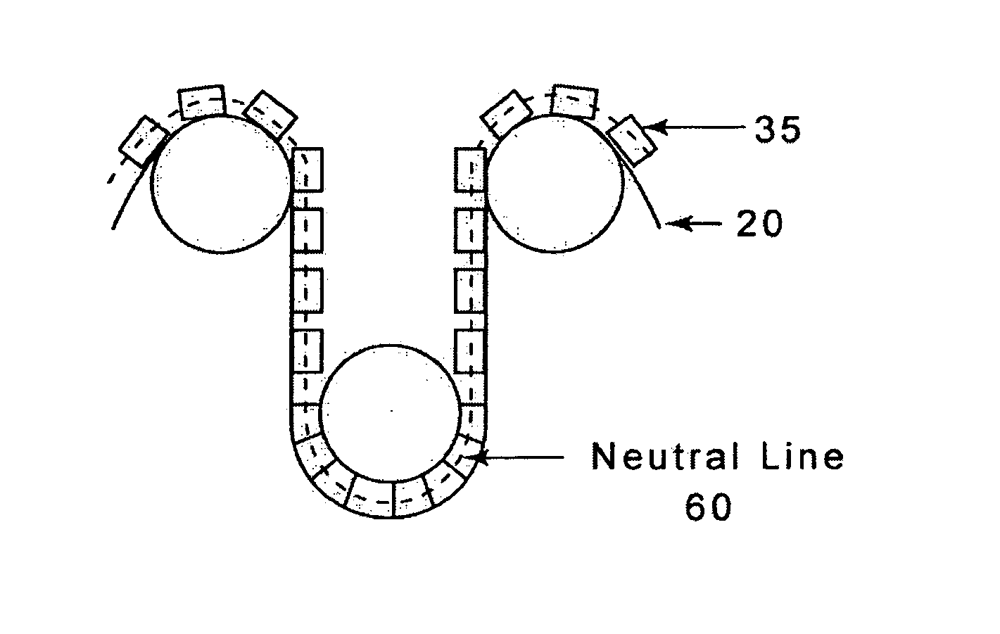
[0034]The present invention relates to a fabric produced for the dryer section of a paper machine that is produced as a nonwoven product using various different raw stock materials. The present fabric is an alternative to typical dryer fabrics which are woven using polymeric monofilament or multifilament yarns or spiral-link dryer fabrics.

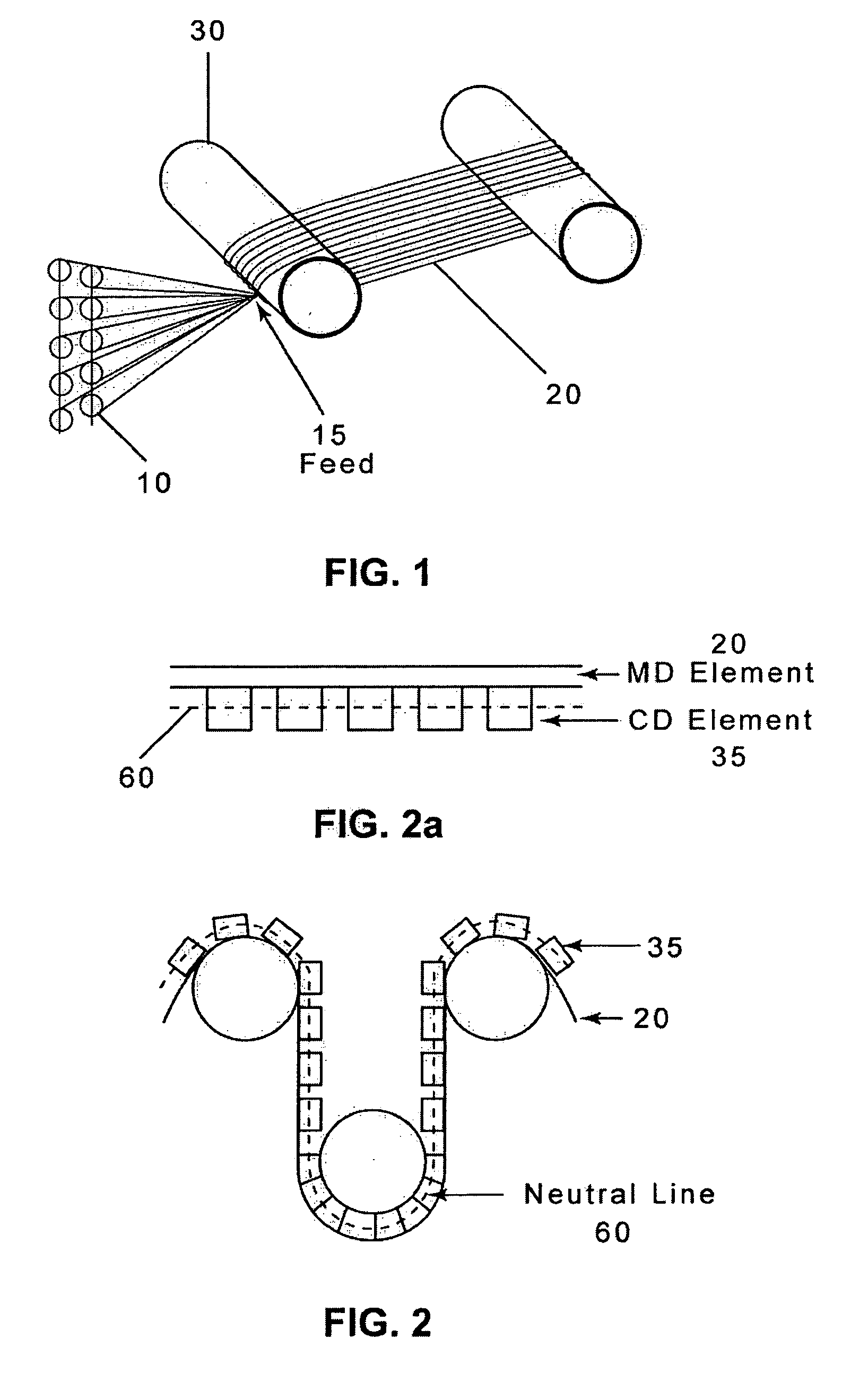
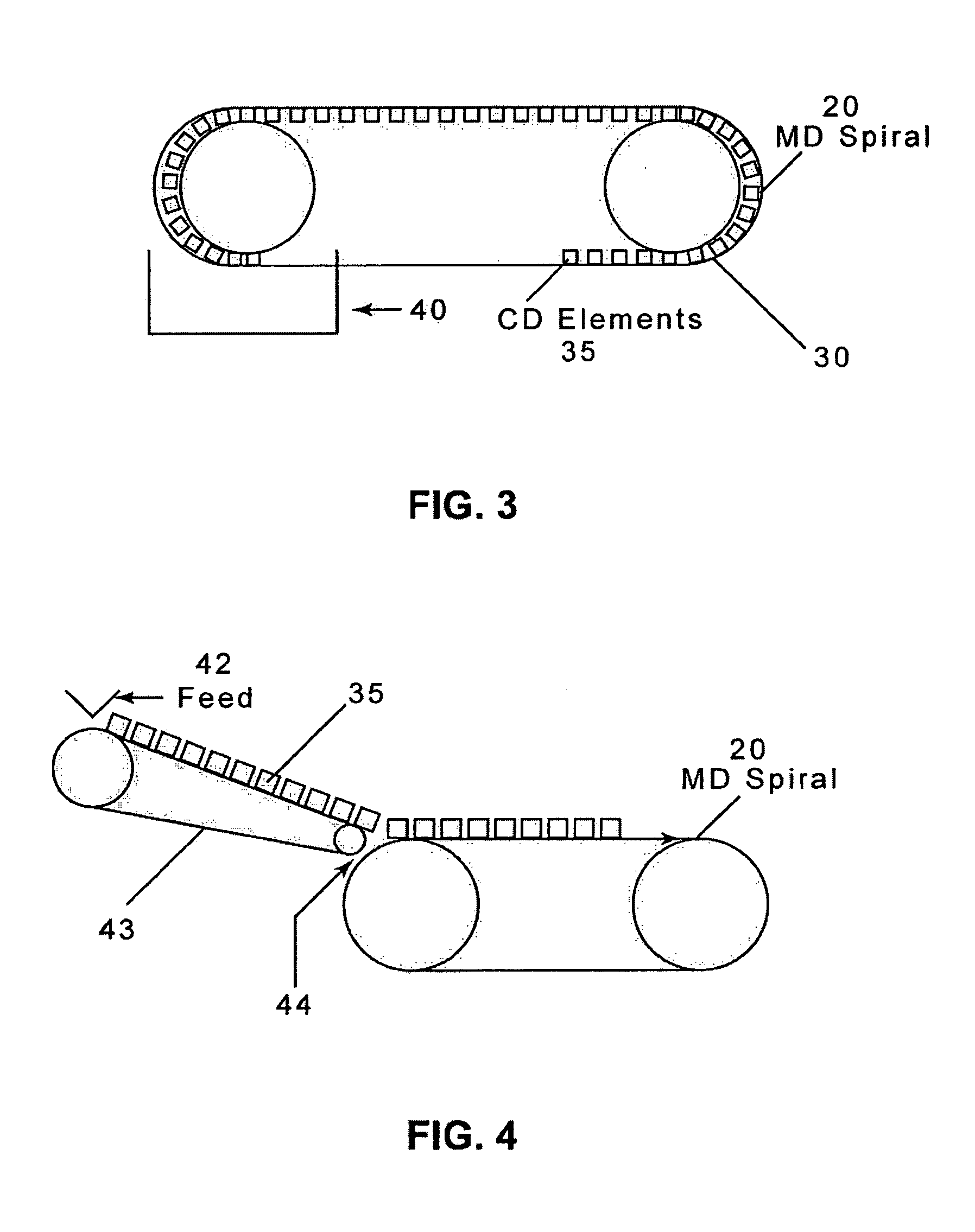
[0035]Specifically, the present fabric has a spiral wound machine direction (MD) base layer of raw stock which is wound around two parallel cylinders until the desired length and width is achieved. This spiral winding technique is similar to that taught in the '656 patent—which is discussed above and is incorporated herein by reference—only the strips of woven material are replaced in the present invention with raw stock material elements. FIG. 1 is an exemplary setup for producing the spiral wound base layer of raw stock elements in accordance with the teachings of the present invention. As shown in FIG. 1, the raw stock material is fed via a deli...


PUM

PropertyMeasurementUnit
lengthaaaaaaaaaa
lengthaaaaaaaaaa
angleaaaaaaaaaa

Abstract

A nonwoven papermaker's fabric, usable in the dryer section of a paper machine, has a spiral wound machine direction (MD) base layer of raw stock which is wound around a pair of parallel rolls or cylinders until the desired length and width is achieved. The spiral wound MD layer is overlaid with a cross-machine direction (CD) layer of similar or dissimilar raw stock and mated by any of a number of means. The spiral wound MD layer can also be mated to another MD layer spiraled in the opposite direction and in one embodiment further mated to a CD layer. The fabric is preferably produced so that its neutral line is oriented toward the paper side of the fabric so that the paper sheet will stretch less than when typical dryer fabrics are used to turn the paper sheet and fabric around the dryer cylinders.

Description

BACKGROUND OF THE INVENTION[0001]1. Field of the Invention[0002]The present invention relates to the papermaking arts. More specifically, the present invention relates to dryer fabrics for the dryer section of a paper machine.[0003]2. Description of the Prior Art[0004]During the papermaking process, a cellulosic fibrous web is formed by depositing a fibrous slurry, that is, an aqueous dispersion of cellulose fibers, onto a moving forming fabric in the forming section of a paper machine. A large amount of water is drained from the slurry through the forming fabric, leaving the cellulosic fibrous web on the surface of the forming fabric.[0005]The newly formed cellulosic fibrous web proceeds from the forming section to a press section, which includes a series of press nips. The cellulosic fibrous web passes through the press nips supported by a press fabric, or, as is often the case, between two such press fabrics. In the press nips, the cellulosic fibrous web is subjected to compressi...

Claims


Application Information

Patent Timeline
Patent Type & Authority Patents(United States)
IPC IPC(8): D21F7/12D21F1/00
CPCD21F1/0036Y10S162/902Y10T428/24116Y10T428/24132Y10T428/24174Y10T428/24612Y10T428/2457Y10T442/30Y10T442/3715Y10T442/60Y10T442/611Y10T442/612Y10T442/627Y10T442/668Y10T442/671D21F1/00D21F3/00
Inventor HANSEN, ROBERT A.
Owner ALBANY INT CORP
Why Eureka
Try Eureka