
Modulated data transfer between a system and its power supply

a technology of moduled data transfer and power supply, which is applied in the direction of modulated carrier systems, single ac networks with different frequencies, signal transmission/receiving via power distribution, etc. it can solve the adverse effect of exposing components outside of the power supply enclosure to dangers, low transmission throughput, and lack of power line networking capabilities of existing power supplies. , to achieve the effect of reducing cost and clutter, eliminating a longer data cable and increasing reliability

Active Publication Date: 2006-01-24
GATEWAY
View PDF11 Cites 33 Cited by
  • Summary
  • Abstract
  • Description
  • Claims
  • Application Information

AI Technical Summary

Benefits of technology

"The present invention is about a power supply that can connect to a network without using extra cables. This is made possible by using modulation techniques to transfer network data over the power output of the power supply. This invention can be used in both internal and external power supplies, reducing cost and clutter while improving reliability. It also eliminates the need for a separate data connector on the system. Overall, this invention provides a more efficient and reliable way to connect to a network without adding extra cables."

Problems solved by technology

For example, an advantage of wireless networking allows the user to roam anywhere within range of an Access Point and a disadvantage of such would be lower transmission throughput.
Existing power supplies have no capabilities for power line networking.
This would have the adverse affect of exposing components outside of the power supply enclosure to the dangers associated with a direct connection to AC power.
This solution would provide protection from the dangerous AC power, but has the problem of creating a power supply that always has the added cost of integrated power line networking.
If every power supply included power line networking, then those customers who did not use power line networking would be burdened by the increased cost and reliability issues associated with extra components integrated into their power supply.
Furthermore, in cases where the power supply is remote, the length of this cable may be quite long and may be confusing to the user.

Method used


Image

  • Modulated data transfer between a system and its power supply
  • Modulated data transfer between a system and its power supply
  • Modulated data transfer between a system and its power supply

Examples


Embodiment Construction

[0017]Reference will now be made in detail to the presently discussed embodiment of the invention, an example of which is illustrated in the accompanying drawings.

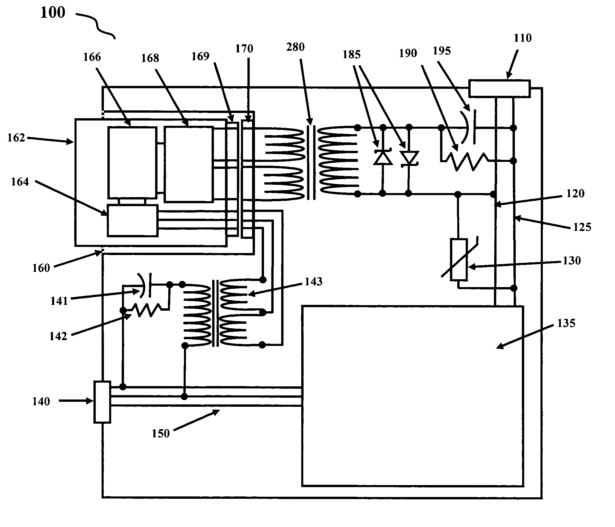
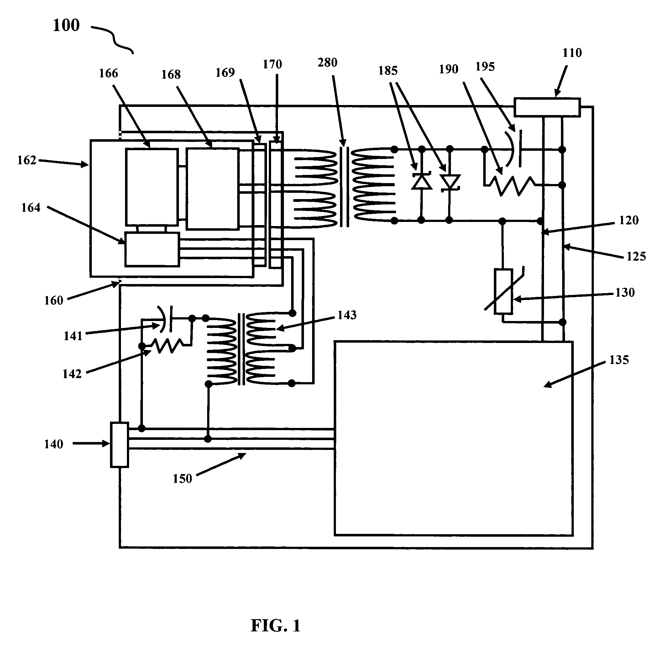
[0018]Referring to FIG. 1, a block diagram of the present invention shown with a modular networking solution is described. The block diagram of the power supply 100 includes an AC input connector 110 that is coupled to a standard power conversion circuit 135 through paths 120 and 125. Power conversion circuit 135 can be any type known in the art, possibly a switching regulator or chopping regulator, for example. Power conversion circuit 135 typically takes as input an AC voltage from 100VAC to 240VAC and converts it to an AC or DC voltage, possibly 3.3VDC, 5VDC, 24VAC, 48VAC, 48VDC, +12VDC and −12VDC, as an example. Power conversion circuit 135 can be a circuit similar or the same as an existing standard power supply conversion circuit, with or without modifications. Power conversion circuit 135 may connect to an power out...


PUM


Abstract

A power supply that includes networking capabilities where networking data is sent and received to and from other systems over the power line and to and from the rest of the system that is being powered over the power supplies output power. The power supply can be included within a system or be external to the system, but in either case, the data from the network is transferred to and from the rest of the system over the same cables that are used to transfer output power from the power supply to the system.

Description

BACKGROUND OF THE INVENTION[0001]This application is related to, and claims priority to U.S. provisional application No. 60 / 443,078, filed Jan. 28, 2003, entitled “APPARATUS AND METHODS OF NETWORKING DEVICES, SYSTEMS AND COMPUTERS VIA POWER LINES”, the entirety of which is incorporated by reference herein, including all of the documents referenced therein. Additionally, this application is related to U.S. application titled, “POWER SUPPLY WITH MODULAR INTEGRATED NETWORKING,” which was filed on even date herewith; application Ser. No. 10 / 762,046 and inventor Mark Rapaich. Additionally, this application is related to U.S. application titled, “HOME POWER LINE NETWORK CONNECTED PHONE,” which was filed on even date herewith; Ser. No. 10 / 761,994 and inventor Frank Liebenow.FIELD OF THE INVENTION[0002]The present invention generally relates to the field of power supplies where the power supply serves not only as a conduit for power coming into a system, but also serves as a conduit for net...

Claims


Application Information

Patent Timeline
Patent Type & Authority Patents(United States)
IPC IPC(8): H04M11/04G06F1/26G06F3/00G06F15/16G06F15/173G08B23/00H02B1/056H02M1/00H04B1/38H04M1/00
CPCG06F1/26G06F1/266H04B3/54H04B3/542H04B2203/5483H04B2203/5416H04B2203/5454H04B2203/547
Inventor THOMAS, KEITH
Owner GATEWAY
Learn More