

Color image processing apparatus and pattern extracting apparatus
a color image and extracting apparatus technology, applied in image enhancement, instruments, character recognition, etc., can solve the problems of large memory resources needed for the process, inability to accurately extract the contour of an area, and long time for generating color separated images, so as to improve the extracting accuracy of the title, improve the reading accuracy, and speed up the
- Summary
- Abstract
- Description
- Claims
- Application Information
AI Technical Summary
Benefits of technology
Problems solved by technology
Method used
Image

Examples
first embodiment
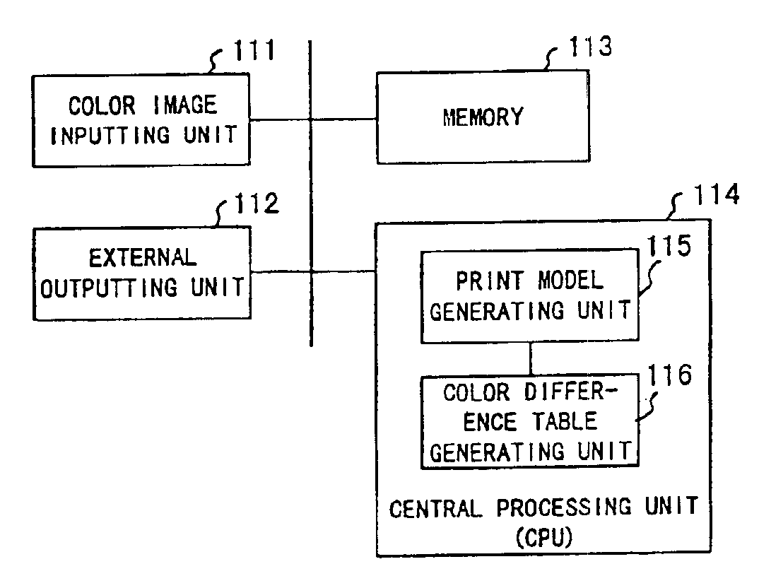
[0180]FIG. 3 is a block diagram showing the structure of a pattern extracting apparatus according to the present invention.
[0181]In FIG. 3, a color information calculating unit 1 calculates color information of a pattern of an input image. A geometry information calculating unit 2 calculates geometry information of a pattern of an input image. A categorizing unit 3 categorizes a pattern of an input image corresponding to the color information calculated by the color information calculating unit 1 and the geometry information calculated by the geometry information calculating unit 2. The color information is for example a color of a pattern in color space. The geometry information is for example the size of a particular pattern, the position of a particular pattern in an input image, or the relation between positions of a particular pattern and another pattern.
[0182]When a pattern of an input image is categorized, the geometry information of the pattern is also used along with the co...
second embodiment
[0184]FIG. 4 is a block diagram showing the structure of a pattern extracting apparatus according to the present invention.
[0185]In FIG. 4, a clustering unit 11 clusters pixels of an input image corresponding to color information of adjacent pixels. A grouping unit 12 groups clusters corresponding to the color information and geometry information of each cluster obtained by the clustering unit 11.
[0186]Thus, when pixels of an input image are clustered, color information of a considered pixel is compared with color information of each of adjacent pixels. Thus, it is not necessary to compare color information of all pixels of the input image.
[0187]When all the pixels of the input image are compared with each other, the number of times of the comparing process of color information of each pixel amounts to the square of the number of pixels of the input image. In contrast, when the color information of a particular pixel is compared with the color information of each of adjacent pixels,...
third embodiment
[0190]FIG. 5 is a block diagram showing the structure of a pattern extracting apparatus according to the present invention.
[0191]In FIG. 5, a color difference calculating unit 21 calculates the color difference of adjacent pixels in an area represented by a predetermined color. A threshold value assigning unit 22 assigns a threshold value corresponding to the color difference calculated by the color difference calculating unit 21. A labeling unit 23 labels pixels adjacent to a pixel represented by a predetermined color corresponding to the threshold value assigned by the threshold value assigning unit 22.
[0192]It is assumed that an input image is obtained from a document printed by the halftone printing method and that the colors of patterns of the input image are represented in a combination of the sizes of dots of basic colors. Since the sizes of dots of the basic colors are small, when one color is represented in a combination of the sizes of dots of the basic colors, even if the...
PUM
 Abstract
Description
Claims
Application Information