Multi-carrier communication apparatus

a communication apparatus and carrier technology, applied in the direction of transmission monitoring, frequency-division multiplex, orthogonal multiplex, etc., can solve the problems of serious degradation of communication, affect the state of the channel used, and affect communication quality, so as to suppress the unnecessary transmission of a reference signal and high communication quality

Inactive Publication Date: 2006-01-24
KK TOSHIBA
View PDF9 Cites 13 Cited by
  • Summary
  • Abstract
  • Description
  • Claims
  • Application Information

AI Technical Summary

Benefits of technology

[0008]It is an object of the invention to provide a multi-carrier communication apparatus capable of realizing high communication quality irrespective of changes in the channel, while suppressing the unnecessary transmission of a reference signal.

Problems solved by technology

On the other hand, as radio is affected by the state of the airwaves, this affects the state of the channel used, thus also the communication quality.
Communication can be seriously degraded, due to the phenomenon of multi-reflection radio propagation (multi-path).
Accordingly, the communication quality may significantly degrade.
Also, the redundant reference signal is transmitted, resulting in increasing the redundancy of the transmission.

Method used


Image

  • Multi-carrier communication apparatus
  • Multi-carrier communication apparatus
  • Multi-carrier communication apparatus

Examples


first embodiment

(First Embodiment)

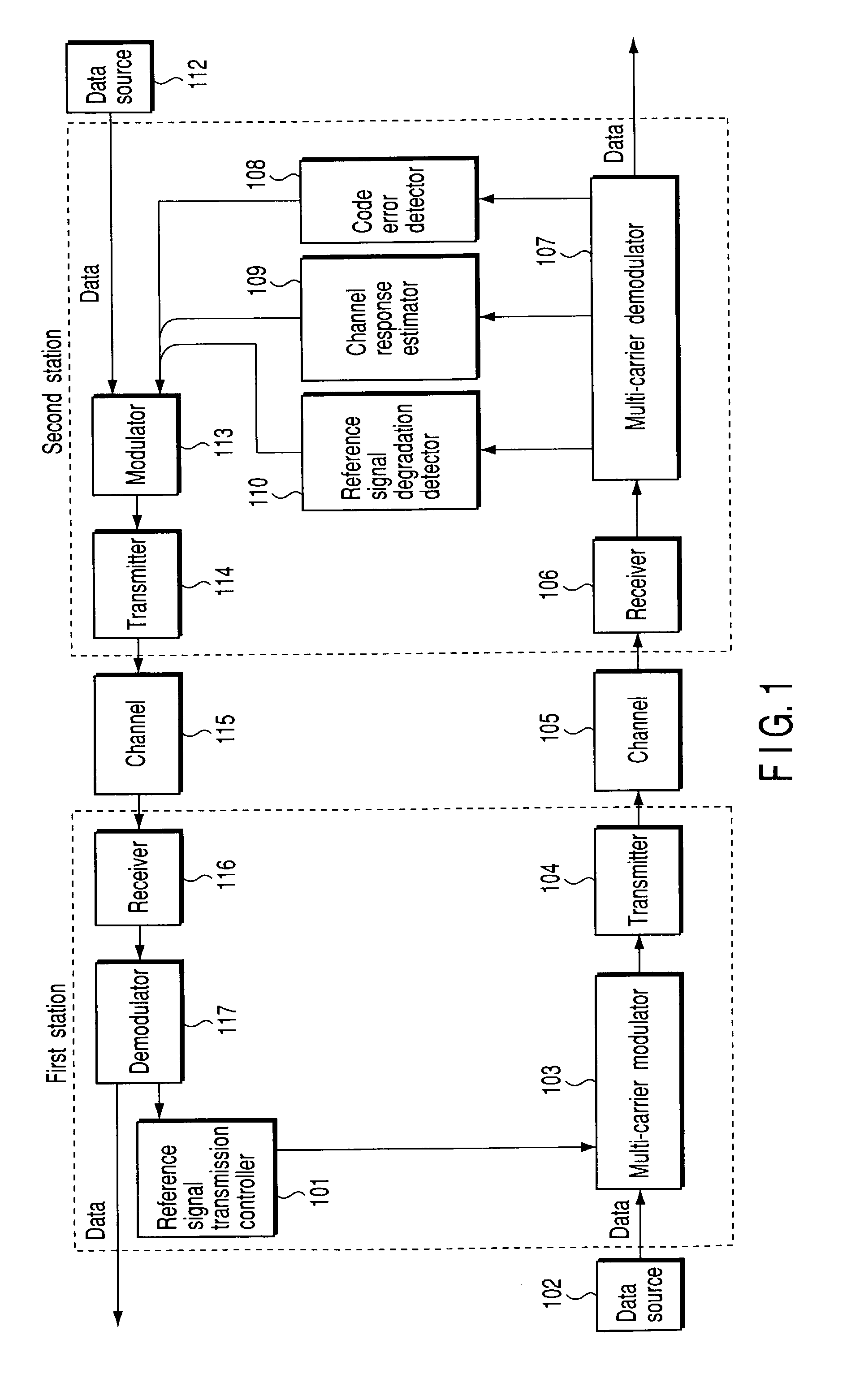
[0025]FIG. 1 shows a multi-carrier transmission system according to a first embodiment of the invention. As shown, the multi-carrier transmission system comprises a station 1 (self-station) as a multi-carrier communication apparatus according to the invention, and a destination station 2 that communicates with the self-station 1. In this embodiment, the transmission pattern of a reference signal, which is inserted in the data transmitted from the station 1 to the station 2, is controlled on the basis of the signal received by the station 2 (i.e., the signal transmitted from the station 1 to the station 2).

[0026]Firstly, in the station 1, a reference signal and reference signal transmission pattern data output from a reference signal transmission controller 101, and transmission data output from a data source 102 are input to a multi-carrier modulator 103. The multi-carrier modulator 103 modulates the transmission data into plural subcarriers (multi-carrier) by mult...

second embodiment

(Second Embodiment)

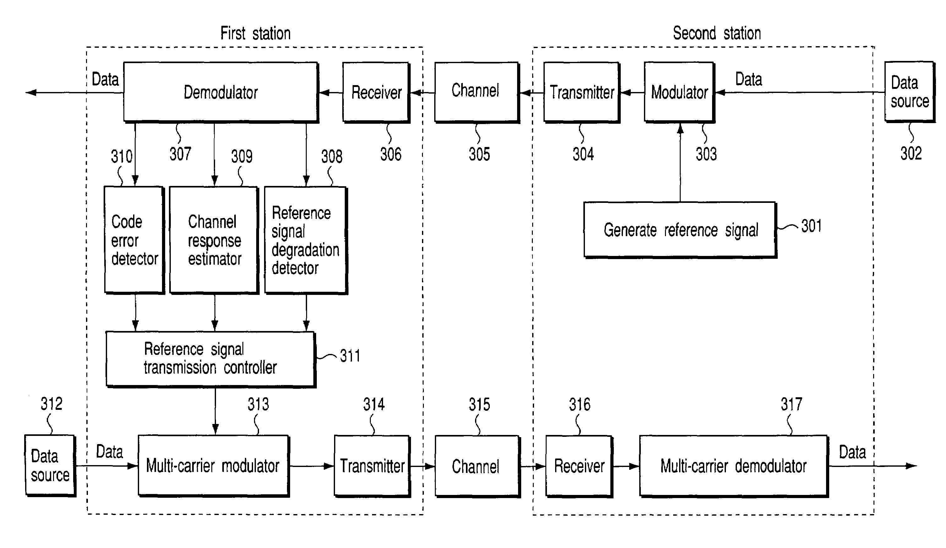
[0037]FIG. 3 shows a multi-carrier transmission system according to a second embodiment of the invention, which comprises, as in the first embodiment, a station 1 (self-station) as a multi-carrier communication apparatus according to the invention, and a destination station 2 that communicates with the self-station 1. In this embodiment, the transmission pattern of a reference signal, which is inserted in the data transmitted from the station 1 to the station 2, is controlled on the basis of the signal received by the station 2 (i.e., the signal transmitted from the station 1 to the station 2).

[0038]Firstly, in the station 2, a predetermined reference signal output from a reference signal generator 301, and data output from a data source 302 are input to a modulator 303, where they are subjected to predetermined modulation. The signal output from the modulator 303 is input to a transmitter 304, where it is converted into a signal suitable for propagation through a...

third embodiment

(Third Embodiment)

[0085]Although in the above-described embodiments, the reference signal pattern (e.g., reference signal transmission interval) is controlled on the basis of the communication quality (code error rate) or response (response power) of each subcarrier, it may be controlled on the basis of the communication quality or response of each of the subcarrier groups that each include plural subcarriers.

[0086]FIG. 9 shows a predetermined number of subcarrier groups, into which a number N of subcarriers (N is set to 8 in this embodiment for facilitating the description) are divided. Specifically, subcarriers SC1–SC5 form a subcarrier group A, and subcarriers SC6–SC8 form a subcarrier group B. The subcarriers may be divided in a preset manner, or may be dynamically divided on the basis of, for example, the correlation described referring to FIG. 6.

[0087]The reference signal transmission pattern is controlled in units of subcarrier groups on the basis of respective control indexe...


PUM


Abstract

A multi-carrier communications apparatus which communicates between a first station and a second station as a destination station using a reference signal used for estimating a state of a channel, the multi-carrier communications apparatus comprising a multi-carrier modulator which modulates data on a plurality of subcarriers, a transmission unit configured to transmit the reference signal together with the data modulated to the destination station every subcarrier, and a control unit configured to control a reference signal transmission pattern according to a given communication condition, the reference signal transmission pattern including a transmission interval of the reference signal transmitted by the transmission unit.

Description

CROSS-REFERENCE TO RELATED APPLICATIONS[0001]This application is based upon and claims the benefit of priority from the prior Japanese Patent Application No. 2001-295107, filed Sep. 26, 2001, the entire contents of which are incorporated by reference.BACKGROUND OF THE INVENTION[0002]1. Field of the Invention[0003]The present invention relates to a multi-carrier communication apparatus for use in a multi-carrier transmission system that is used to estimate the state of the channel using a reference signal.[0004]2. Description of the Related Art[0005]At present, the role of data transmission by radio is gaining more and more importance, due to the popularization of cellular phones, wireless LANs, and digital broadcast. In light of portability, ease of installation and cost, radio data transmission is significantly advantageous over wired data transmission. On the other hand, as radio is affected by the state of the airwaves, this affects the state of the channel used, thus also the co...

Claims


Application Information

Patent Timeline
Patent Type & Authority Patents(United States)
IPC IPC(8): H04B7/00H04J1/00H04B7/26H04J11/00H04L27/26H04W72/04H04W72/08
CPCH04L5/0048H04B17/309H04L25/0226H04L5/006H04L5/0007
Inventor HORISAKI, KOJI
Owner KK TOSHIBA
Why Eureka
Try Eureka