
Front-end arrangements for multiband multimode communication engines

a communication engine and multi-mode technology, applied in the field of front-end topology, can solve the problems of complex construction and design of the front-end of multi-band multi-mode engines, consuming a significant amount of electrical current, and needing many control lines, so as to reduce the complexity of the frond-end design, reduce the number of matching elements and switching components, and reduce the current consumption and loss in the front-end engine.

Active Publication Date: 2006-01-24
NOKIA TECHNOLOGLES OY
View PDF11 Cites 59 Cited by
  • Summary
  • Abstract
  • Description
  • Claims
  • Application Information

AI Technical Summary

Benefits of technology

The present invention provides a solution for reducing complexity in the design of frond-end modules for multi-band communication devices. By combining two or more signal paths, the number of matching elements and switching components can be reduced, leading to lower current consumption and losses in the front-end engines. The invention also includes filters, baluns, and signal amplifiers to improve the isolation and filtering of signals in different frequency ranges. The invention also provides a method for reducing reception loss in a portable communication device by using different antennas for transmitting and receiving signals. Overall, the invention simplifies the design of frond-end modules and improves the performance of multi-band communication devices.

Problems solved by technology

The front-end in multiband, multimode engines, especially those that are designed to meet the requirement of MIMO (multiple-input, multiple-output) and / or diversity functionality, is usually very complex in construction and design.
Because the front-end generally comprises many switches, it consumes a significant amount of electrical current and needs many control lines.
The front-end architecture is complex and the additional losses in these reception paths occur.

Method used


Image

  • Front-end arrangements for multiband multimode communication engines
  • Front-end arrangements for multiband multimode communication engines
  • Front-end arrangements for multiband multimode communication engines

Examples


Embodiment Construction

[0073]The upper (2 GHz) GSM band Rx and Tx performance in a multiband, multimode mobile terminal (or a communicator device and the like) can be improved by relocating some of the GSM and W-CDMA paths in the front-end of the engine. The mobile terminal 1 is schematically shown in FIG. 9, which shows a transceiver front-end 2 comprising a first module 4 operatively connected to an antenna 10, and a second module 8 operatively connected to an antenna 20. The second module 8 may have one or more antenna 20′ for Rx MIMO / diversity purposes.

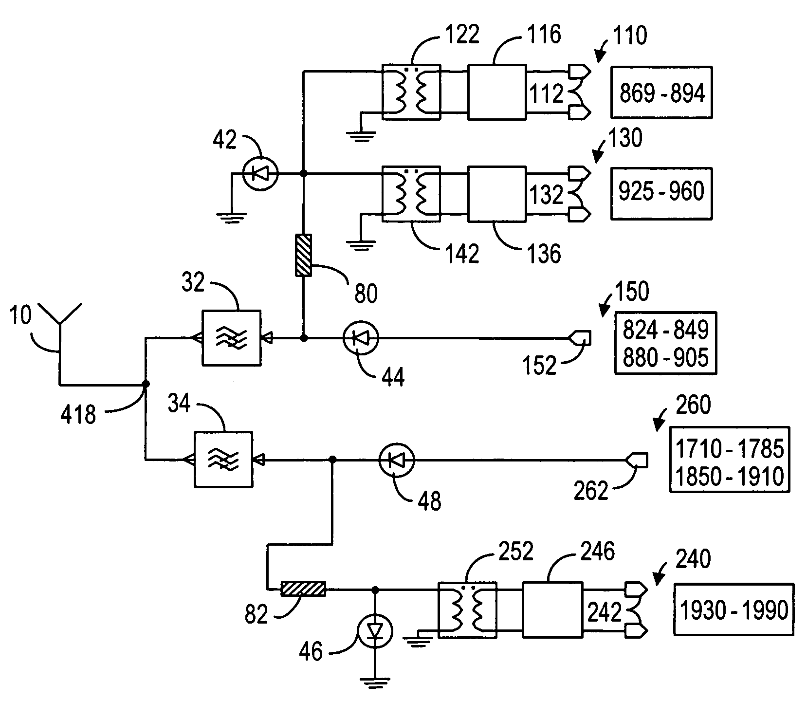
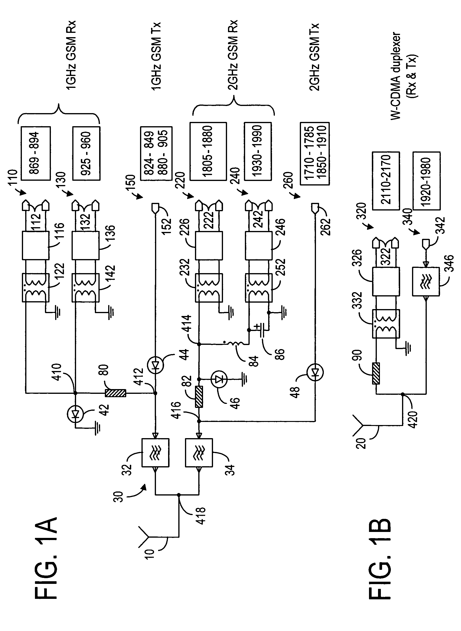
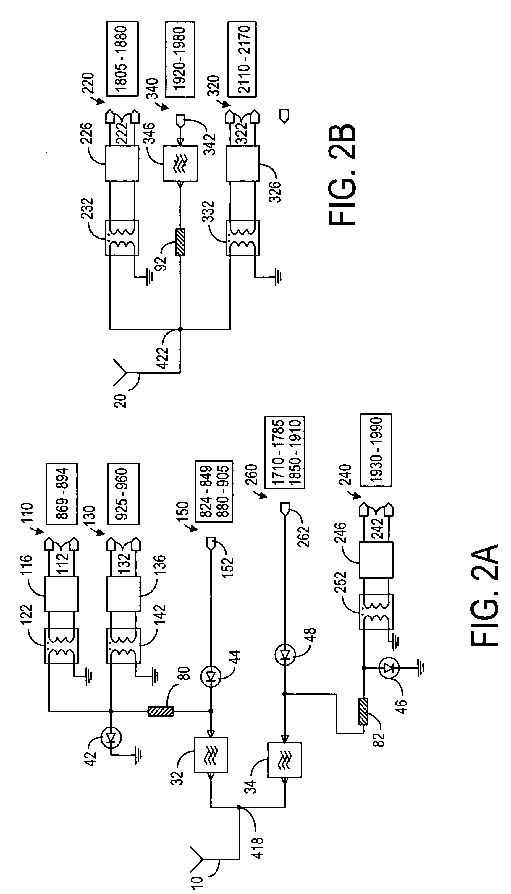
[0074]According to one embodiment of the present invention, the 1800GSM Rx (1805–1880 MHz) is moved from the antenna switch to the W-CDMA duplexer. As shown in FIG. 2a, the 2 GHz part of the GSM module has only one Rx path 240: 1900GSM Rx (1930–1990 MHz). As such, the matching elements 84 and 86 (see FIG. 1a) can be eliminated. The 1800GSM Rx path 220 shares the upper band antenna 20 of the W-CDMA module, as shown in FIG. 2b. Because of the different op...


PUM


Abstract

A receive front-end module in a multi-band communication device. The communication device comprises a plurality of signal paths for receiving and transmitting communication signals in a plurality of frequency bands in GSM and W-CDMA modes. The signal paths in the receive front-end module are operatively connected to a common feed point, which is connected to one of the RF antennas of the communication device, and the signal paths are selected such that none of the frequency bands for receiving communication signals in the receive front-end module are overlapping. If the communication device also transmits the communication signal in at least one transmit frequency range partially overlapping with one of the frequency bands in the receive front-end module, switching means is provided to at least one of signal paths in the receive front-end module for providing cross-band isolation between the transmitted and received communication signals.

Description

CROSS REFERENCES TO RELATED APPLICATIONS[0001]This application is related to U.S. patent application Ser. No. 10 / 118,657, filed Apr. 8, 2002, and assigned to the assignee of the present application. This application is also related to patent applications Ser. No. 10 / 688,807 and Ser. No. 10 / 688,181, assigned to the assignee of the present application and filed even date herewith.FIELD OF THE INVENTION[0002]The present invention relates generally to front-end topology and, more particularly, to front-end arrangement for multiband and / or multimode mobile cellular handset electronics.BACKGROUND OF THE INVENTION[0003]The term “front-end” as used in this disclosure, means the components and functions between the antennas and the power amplifiers or RF-ASIC (radio frequency application specific integrated circuit), but some front-end modules may also include power amplifiers. The front-end in multiband, multimode engines, especially those that are designed to meet the requirement of MIMO (...

Claims


Application Information

Patent Timeline
Patent Type & Authority Patents(United States)
IPC IPC(8): H04M1/00H04B1/00
CPCH04B1/0057H04B1/48H04B1/18H04B1/0064H04B7/00H04M1/00
Inventor ELLA, JUHAMARTIN, NIGELKYLAKOSKI, JANNE
Owner NOKIA TECHNOLOGLES OY
Learn More