Steam cleaning apparatus

Inactive Publication Date: 2006-01-31
ARIETE
View PDF8 Cites 17 Cited by
  • Summary
  • Abstract
  • Description
  • Claims
  • Application Information

AI Technical Summary

Benefits of technology

[0002]As is known, steam cleaning apparatus exist, comprising an upper handle, an intermediate pole and a bottom head housing a sliding unit which supplies the steam to a rag, a cloth or the like, which is fixed to said sliding unit. The water necessary for production of the steam is supplied to said head by means of pipes which pass inside or outside the pole and is drawn from a reservoir which may be located directly inside the head, inside the handle or outside thereof. In all these cases, the bottom head has a heater or boiler which converts the water into steam. One of t

Problems solved by technology

One of the main drawbacks of this apparatus is the difficulty in regulating the quantity of steam which is to be produced by the sli

Method used


Image

  • Steam cleaning apparatus
  • Steam cleaning apparatus
  • Steam cleaning apparatus

Examples


Embodiment Construction

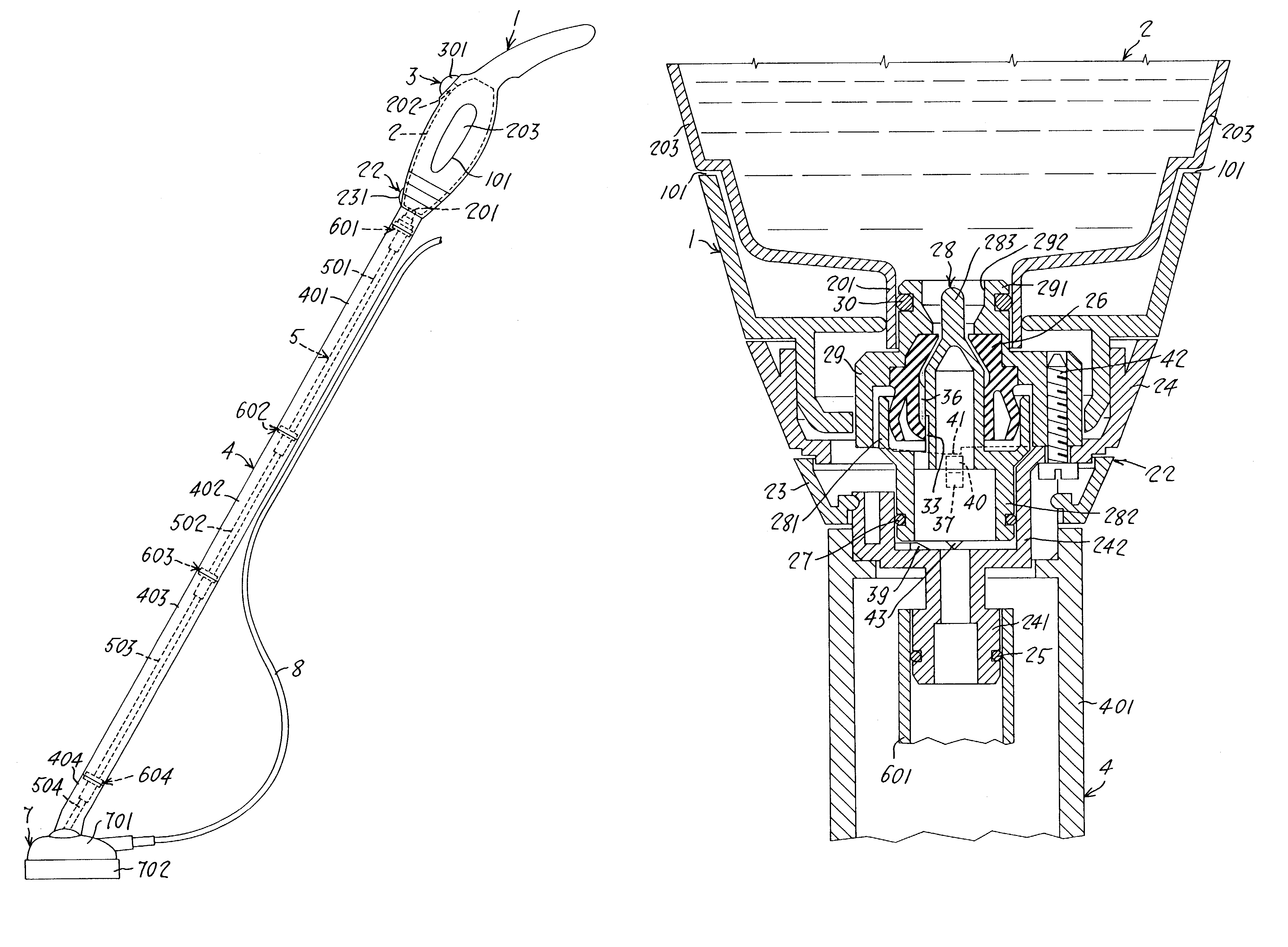
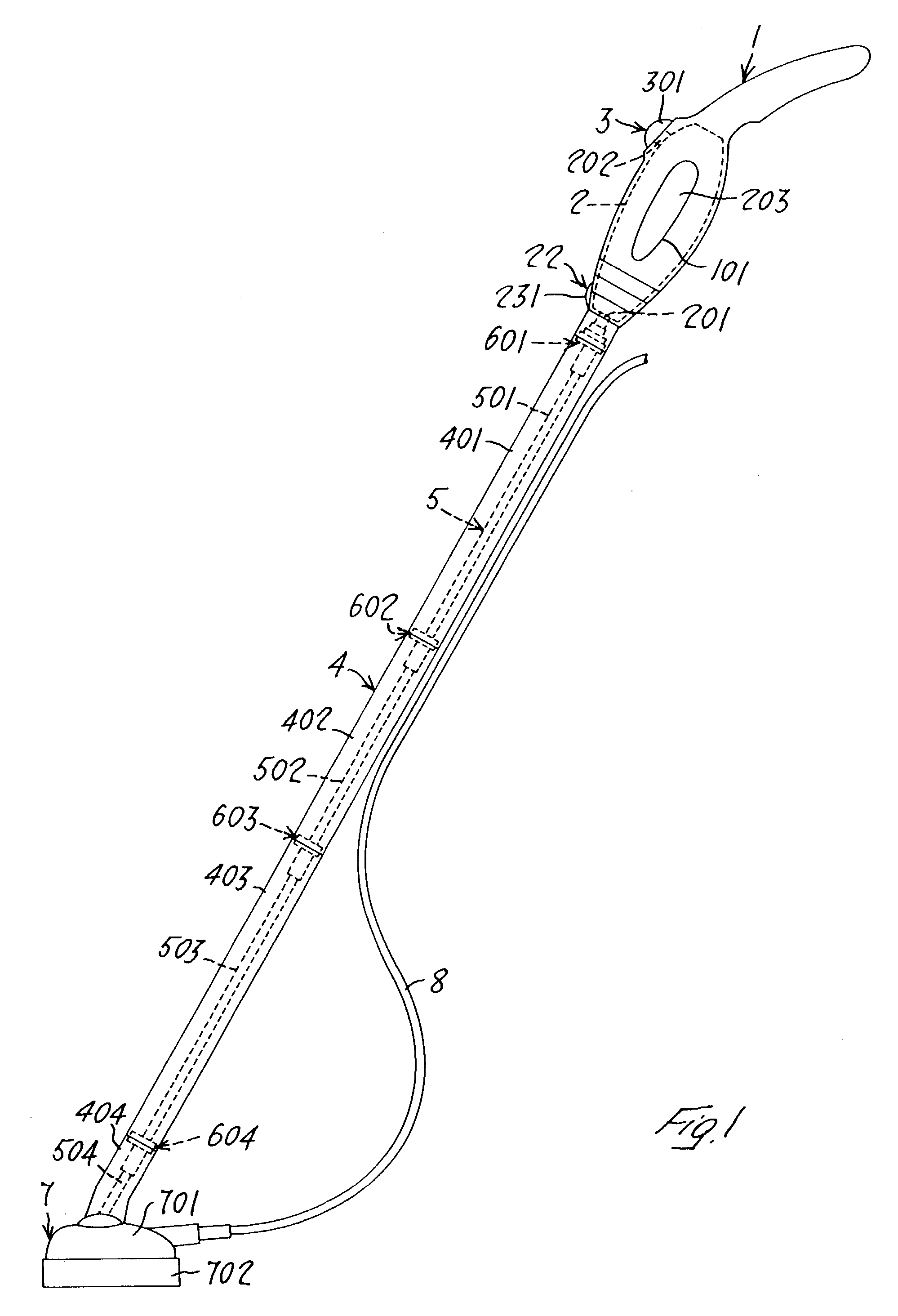
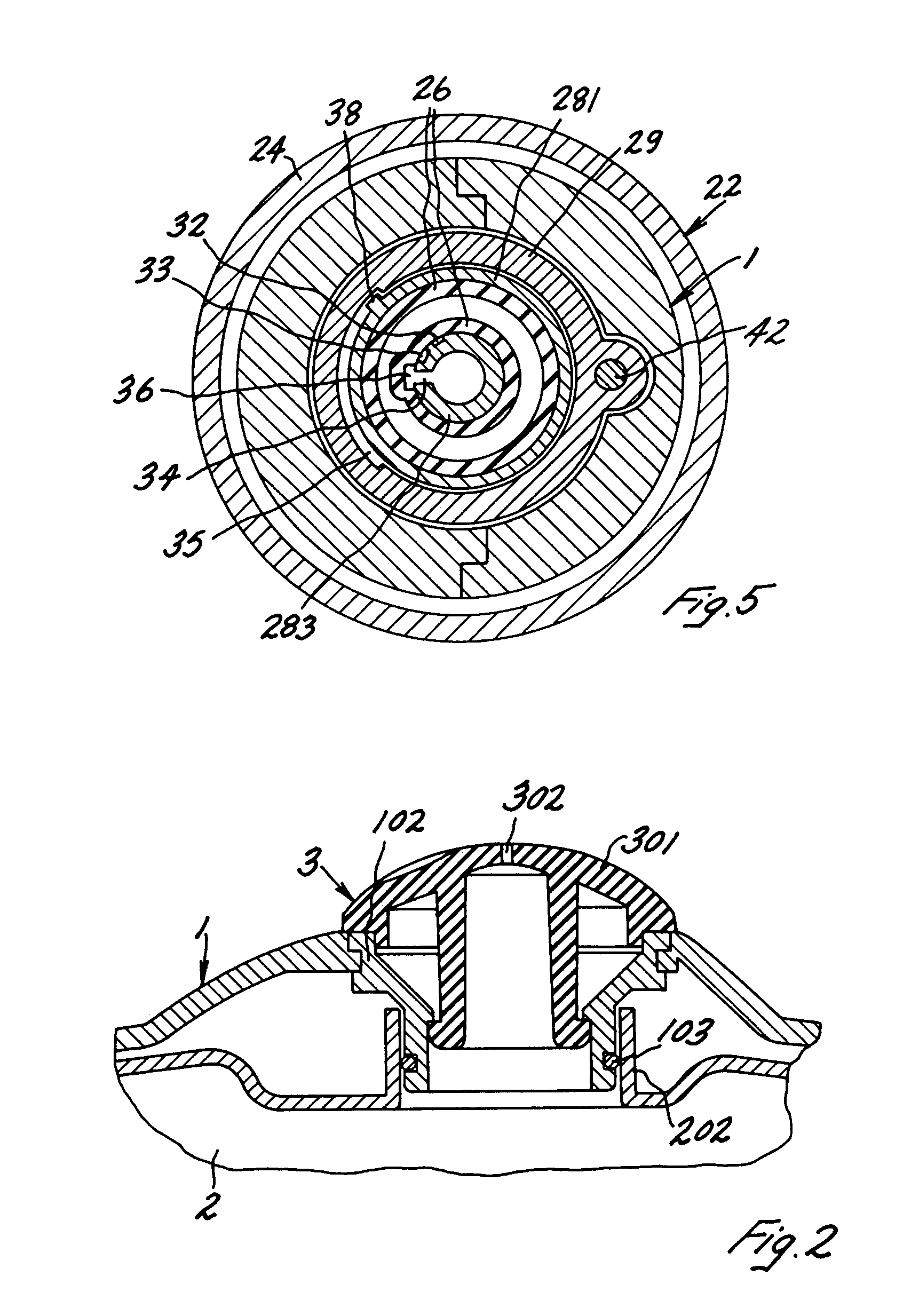
[0012]With reference to the accompanying drawings, FIG. 1 shows a steam cleaning apparatus according to the present invention, comprising a handle 1 inside which a water storage reservoir 2 is housed. This handle 1 also houses internally a water loading device 3 provided with associated cap 301 and a device 22 for regulating the steam produced by an instantaneous steam generator housed inside a bottom cleaning head 7. This loading device 3 is positioned opposite an upper mouth 202 for loading the water inside said reservoir 2, while said regulating device 22 is positioned opposite a bottom mouth 201 for discharging the water from said reservoir 2. The handle 1 comprises, in the vicinity of its sides, two openings 101 which render visible two sections 203 of the reservoir 2, which may be made of transparent material for verification of the water level inside the reservoir 2 or, alternatively, the reservoir itself may be made of transparent material. A sectional pole 4 is connected in...


PUM


Abstract

Steam cleaning apparatus, comprising an upper handle, an intermediate pole and a bottom head for production and supplying of steam, provided with an instantaneous steam generator, a water reservoir housed on the top of said pole in the region of the handle, a duct for transferring the water from said reservoir to said head and a water loading device housed on an associated loading mouth formed above said reservoir, further comprising a steam regulating device provided with a fixed bushing having a hollow bottom end sealingly engaged on the top end of a sectional pole and a valve body fixed inside said bushing, the top part of said valve body being sealingly engaged on a discharge mouth of said reservoir and provided with a through-hole able to be opened and closed in an adjustable manner by a valve which can be actuated on the outside of the device by means of suitable means movable with respect to said bushing.

Description

BACKGROUND AND SUMMARY OF THE INVENTION[0001]The present invention relates to a steam apparatus for cleaning horizontal surfaces, in particular floors.[0002]As is known, steam cleaning apparatus exist, comprising an upper handle, an intermediate pole and a bottom head housing a sliding unit which supplies the steam to a rag, a cloth or the like, which is fixed to said sliding unit. The water necessary for production of the steam is supplied to said head by means of pipes which pass inside or outside the pole and is drawn from a reservoir which may be located directly inside the head, inside the handle or outside thereof. In all these cases, the bottom head has a heater or boiler which converts the water into steam. One of the main drawbacks of this apparatus is the difficulty in regulating the quantity of steam which is to be produced by the sliding unit for cleaning. This heater, moreover, increases considerably the overall volume and reduces the compactness of the apparatus.[0003]...

Claims


Application Information

Patent Timeline
IPC IPC(8): A47L5/00F17C7/04A47L11/00A47L11/02A47L11/34B08B3/00F16K31/46
CPCA47L11/34A47L11/4086F16K31/465B08B3/00A47L13/225B08B2230/01
Inventor ROSA, CARLOBARGAGNA, ROBERTO
Owner ARIETE
Why Eureka
Try Eureka