
Lip for an excavation bucket

a technology for excavation buckets and spouting plates, which is applied in the direction of mechanical machines/dredgers, soil shifting machines/dredgers, constructions, etc., can solve the problems of reducing the fatigue strength of the lip, reducing the overall mass of the lip, and prone to heavy weight of the casting. the effect of mass reduction

Inactive Publication Date: 2006-01-31
CATEPILLAR SARL
View PDF18 Cites 61 Cited by
  • Summary
  • Abstract
  • Description
  • Claims
  • Application Information

AI Technical Summary

Benefits of technology

[0007]Typically, the lip includes one additional plate between the upper and lower plates, and the additional plate defines openings along its length for reducing the mass of this plate.

Problems solved by technology

The castings tend to be relatively heavy and consequently contribute significantly to the overall mass of the lip.
A further disadvantage associated with conventional lips for dragline buckets is that the nosepiece castings have to be welded to the lip with transverse welds that extend across the upper and lower surfaces of the lip, and these welds reduce the fatigue strength of the lip.

Method used


Image

  • Lip for an excavation bucket
  • Lip for an excavation bucket

Examples


Embodiment Construction

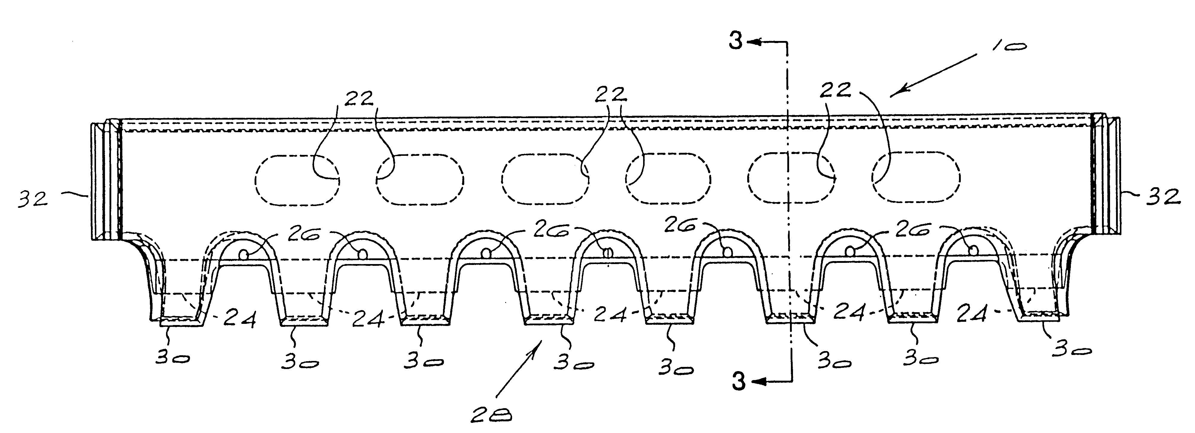
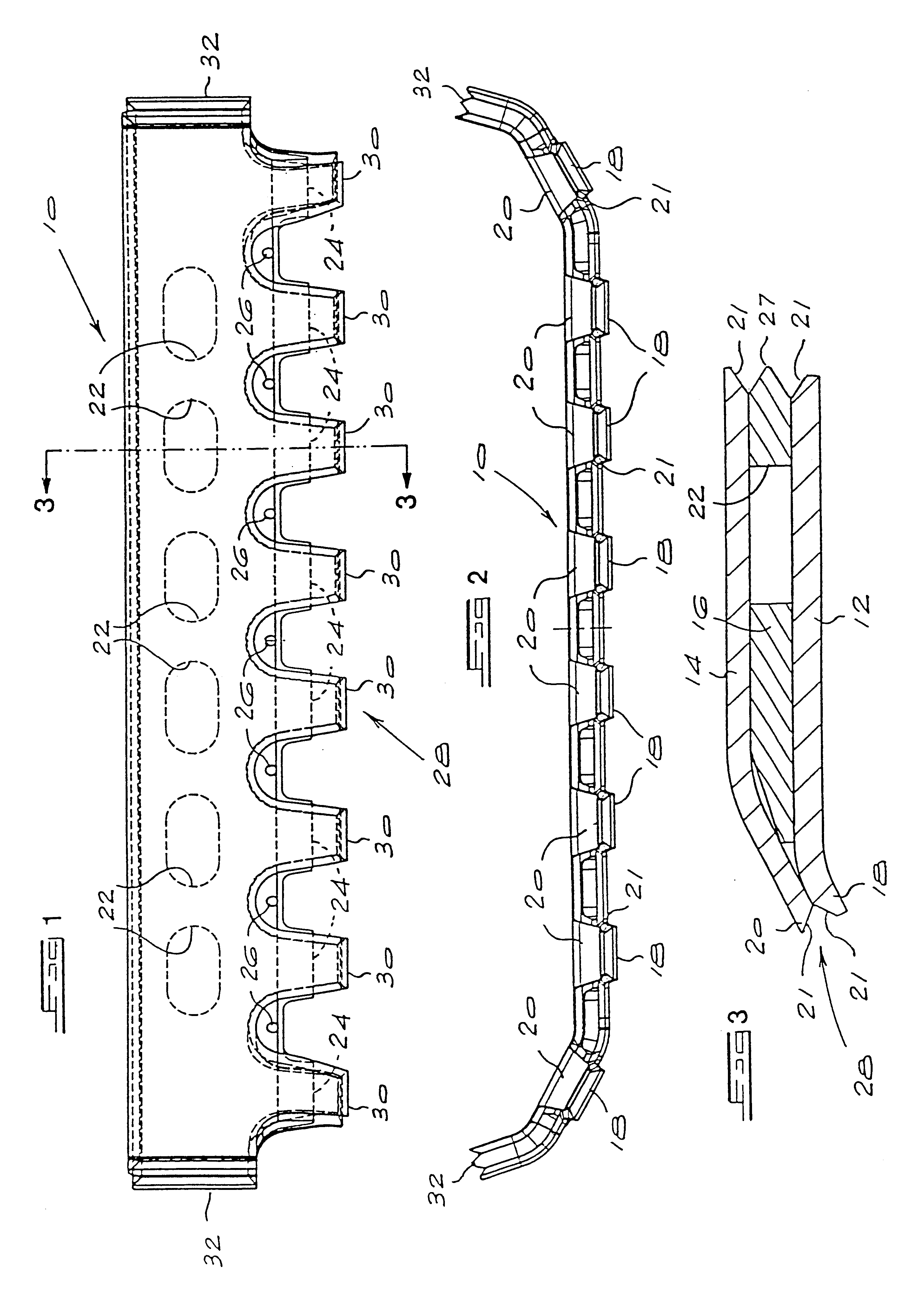
[0016]FIG. 1 of the drawings illustrates a top view of a lip for an excavation bucket according to the present invention. The lip is designated generally with the reference numeral 10 and is formed from three steel plates which are welded together in a manner which is described in more detail below.

[0017]With reference also to FIG. 3 of the accompanying drawings, the steel plates forming the lip 10 include a lower plate 12, an upper plate 14 and a central plate 16 which is sandwiched between the lower and upper plates, as shown. The lower plate and the central plate are formed from a high strength steel having a minimum yield strength of 700 N / mm2, typically WELDOX™ 700D, and the upper plate is formed from an abrasion resistant steel with a minimum hardness of 40 Rockwell C, typically HARDOX™ 400.

[0018]The lower plate 12 defines eight integral projections 18 (see FIG. 2) which are formed by cutting recesses into a front edge of this plate. The projections are inclined downwardly out...


PUM


Abstract

The invention relates to a lip for an excavation bucket. The lip includes a lower plate defining a plurality of integral projections along a front edge thereof, an upper plate and a central plate sandwiched between the lower plate and the upper plate so as to form a laminated structure. The upper plate also defines a plurality of integral projections which together with the projections on the lower plate form tool attachment formations in a serrated front edge of the laminated structure for supporting ground-engaging tools on the lip.

Description

BACKGROUND OF THE INVENTION[0001]THIS invention relates to excavation buckets, and more specifically to a lip for an excavation bucket.[0002]Excavation buckets such as dragline buckets generally have a lip welded to the front of the bucket for supporting a plurality of ground-engaging tools. These lips are usually formed from a single, rolled steel or cast steel plate with a straight front edge, and include a plurality of nosepiece castings which are fixed to the lip so as to project from the front edge of the lip. Ground-engaging tools are mechanically attached to the nosepieces, typically by means of adaptor castings.[0003]The castings tend to be relatively heavy and consequently contribute significantly to the overall mass of the lip. Since the total mass of a loaded dragline bucket is limited by the dragline rated suspended load (RSL), it is desirable to reduce the mass of the bucket so as to allow for an increase in the bucket load and hence the productivity of the dragline.[00...

Claims


Application Information

Patent Timeline
IPC IPC(8): E02F3/36
CPCE02F3/36E02F9/2883E02F3/40
Inventor ZAAYMAN, OSWALD CORNELIUS DANNHAUSERESTERHUYSE, SCHALK WILLEM PETRUS
Owner CATEPILLAR SARL
Learn More