
Automatic gear transmission apparatus

a transmission apparatus and automatic technology, applied in mechanical equipment, gearing control, transportation and packaging, etc., can solve the problems of increasing hardware cost, increasing energy consumption, and relatively high cost of two sets of motors, so as to reduce hardware cost, reduce energy consumption, and reduce space limitation

Inactive Publication Date: 2006-01-31
IND TECH RES INST
View PDF4 Cites 8 Cited by
  • Summary
  • Abstract
  • Description
  • Claims
  • Application Information

AI Technical Summary

Benefits of technology

This solution reduces hardware costs, energy consumption, and spatial requirements while simplifying control, enabling efficient and cost-effective automatic gear transmission.

Problems solved by technology

1. Higher cost of hardware. The conventional automatic gear transmission apparatus needs to use two sets of motors to sequentially proceed “gear selection” and “gear transmission,” so a relatively higher cost will be resulted from utilization of two sets of motors.
2. Higher consumption of energy. Under the operation state of the vehicle, the electromagnetic clutch is actuated frequently thus its energy consumption is relatively higher.
3. Higher cost of control. Some server and feedback driver must be adapted to achieve positioning control for “gear selection” and “gear transmission” actions, so its cost of controlling is relatively higher.
4. Larger limit of space. Since the conventional automatic gear transmission apparatus applies two sets of motors, the space occupied therein is relatively larger thus more restrictions on the position arrangement for each element are caused.

Method used


Image

  • Automatic gear transmission apparatus
  • Automatic gear transmission apparatus
  • Automatic gear transmission apparatus

Examples


Embodiment Construction

[0025]For better recognizing and understanding the characteristics, objectives, and functions of the invention, a detailed description together with accompanying diagrams are presented as follows.

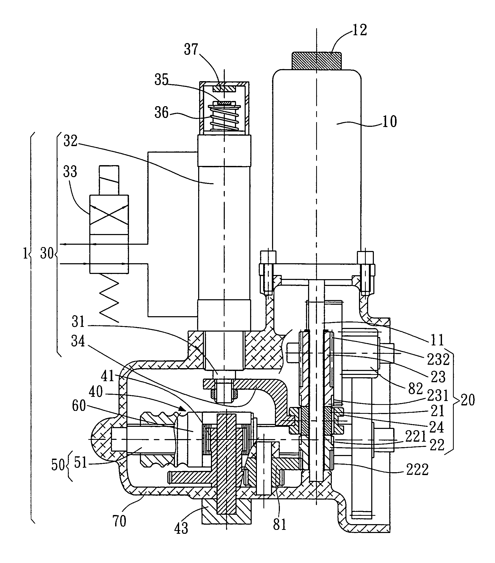
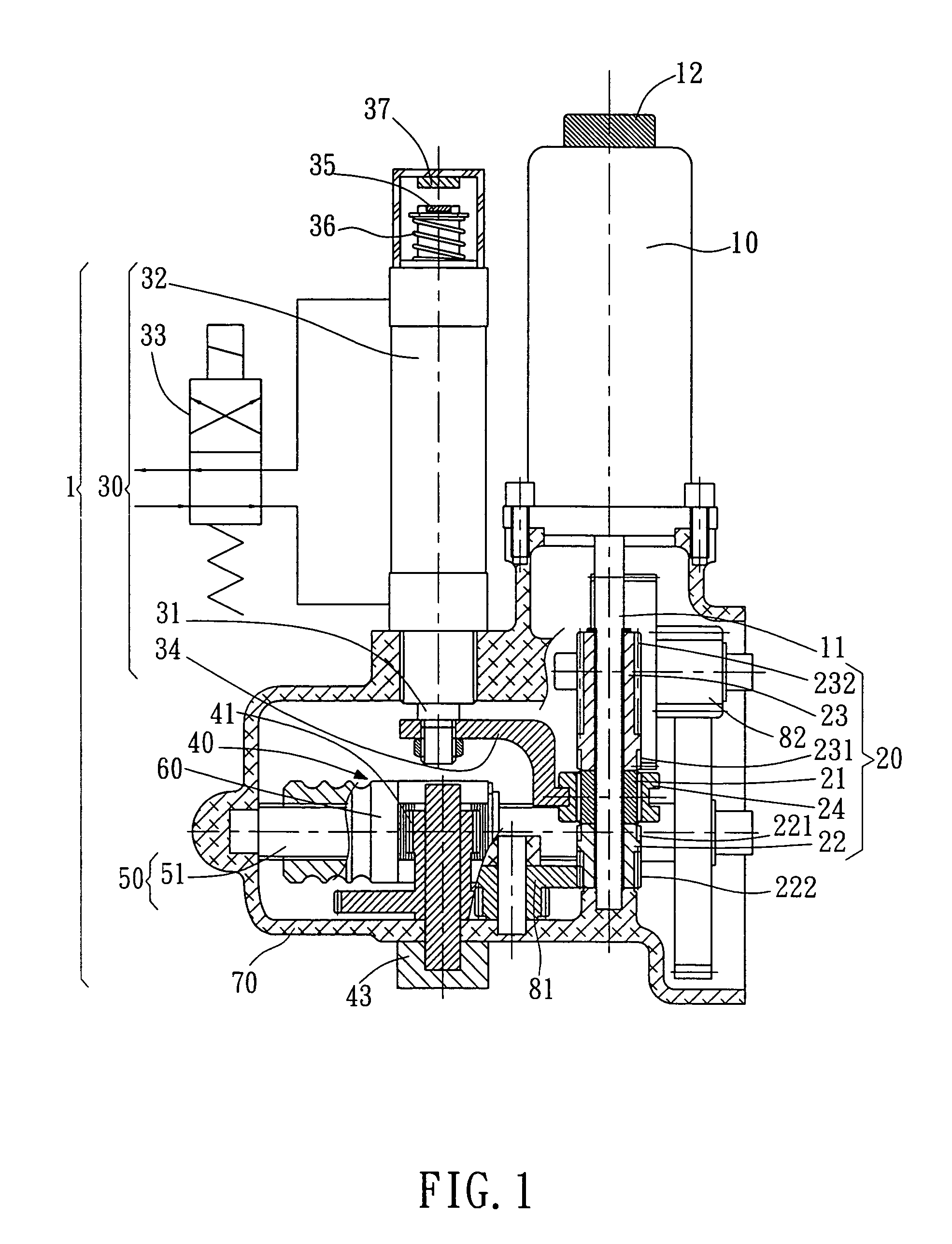
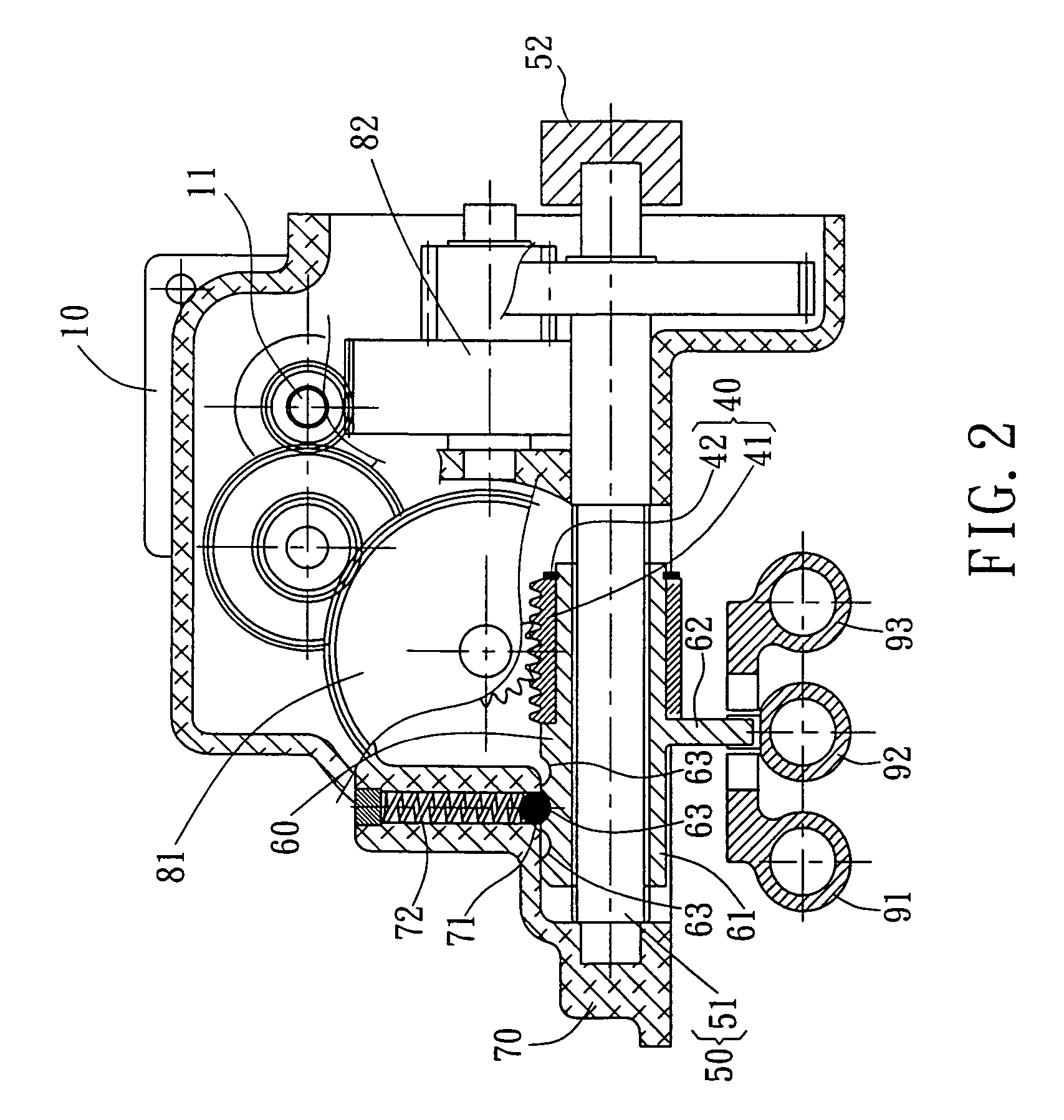
[0026]The automatic gear transmission apparatus disclosed in the invention is mainly cooperated with a manual transmission gearbox (not shown in the figures) with plural transmission positions to provide a speed-changing function of “manual-automatic transmission.” An ordinary manual transmission gearbox mostly includes: a gearbox, comprising plural of gears, and a gear transmission mechanism, comprising several transmission forks. By pushing different transmission forks, the engagements of the gears in the gearbox can be changed to generate different speed-reducing ratios to achieve the effect of speed-changing. By means of the transmission rod operated by the driver or the transmission button pressed by the driver or, according to the electronic control signal generated by the vehicle's c...


PUM


Abstract

An automatic gear transmission apparatus, capable of cooperating with a conventional manual transmission gearbox to provide an automatic gear transmission function. The automatic gear transmission apparatus comprises: a motor, a clutch mechanism, a gear selection mechanism, a gear transmission mechanism, and a sleeve rod. By operation of the clutch mechanism, output power from a single motor can be optionally transmitted out through the gear selection mechanism or the gear transmission mechanism. The power output by the gear selection mechanism can linearly activate the sleeve rod to proceed a gear selection action, while the power output by the gear transmission mechanism can rotationally activate the sleeve rod to proceed a gear transmission action. Therefore, using only a single motor can drive the sleeve rod linearly or rotationally to proceed two actions of gear selection and gear transmission, respectively.

Description

FIELD OF THE INVENTION[0001]The invention relates to an automatic gear transmission apparatus, and in particular to an automatic gear transmission apparatus capable of cooperating with a conventional manual transmission gearbox to provide an automatic gear transmission function, wherein only a single motor is used to proceed two actions of gear selection and gear transmission.BACKGROUND OF THE INVENTION[0002]For the vehicles in the current market, besides two traditional gear transmission systems of manual gear transmission and automatic gear transmission, there is also a popular “manual-automatic transmission” speed-changing system, which not only makes driver enjoy the driving fun of manual transmission, but also makes driver enjoy easy operation and convenience of automatic transmission.[0003]In brief, the basic principle of the so-called “manual-automatic transmission” speed-changing system is arranging a set of automatic transmission apparatus into a general manual transmission...

Claims


Application Information

Patent Timeline
Patent Type & Authority Patents(United States)
IPC IPC(8): F16H59/00B60K17/04B60K20/00F16H59/08F16H61/32
CPCF16H61/32F16H2061/2838Y10T74/2003Y10T74/19251F16H2061/2892
Inventor CHEN, LI-YU
Owner IND TECH RES INST
Learn More