
Drain line re-perforator device

a technology of reperforator and drain line, which is applied in the direction of sewage draining, tube shearing machine, borehole/well accessories, etc., can solve the problems of system inoperableness, deterioration of aggregate materials, clogging or damage,

Inactive Publication Date: 2006-01-31
RUBINO DANIEL L
View PDF25 Cites 6 Cited by
  • Summary
  • Abstract
  • Description
  • Claims
  • Application Information

AI Technical Summary

Benefits of technology

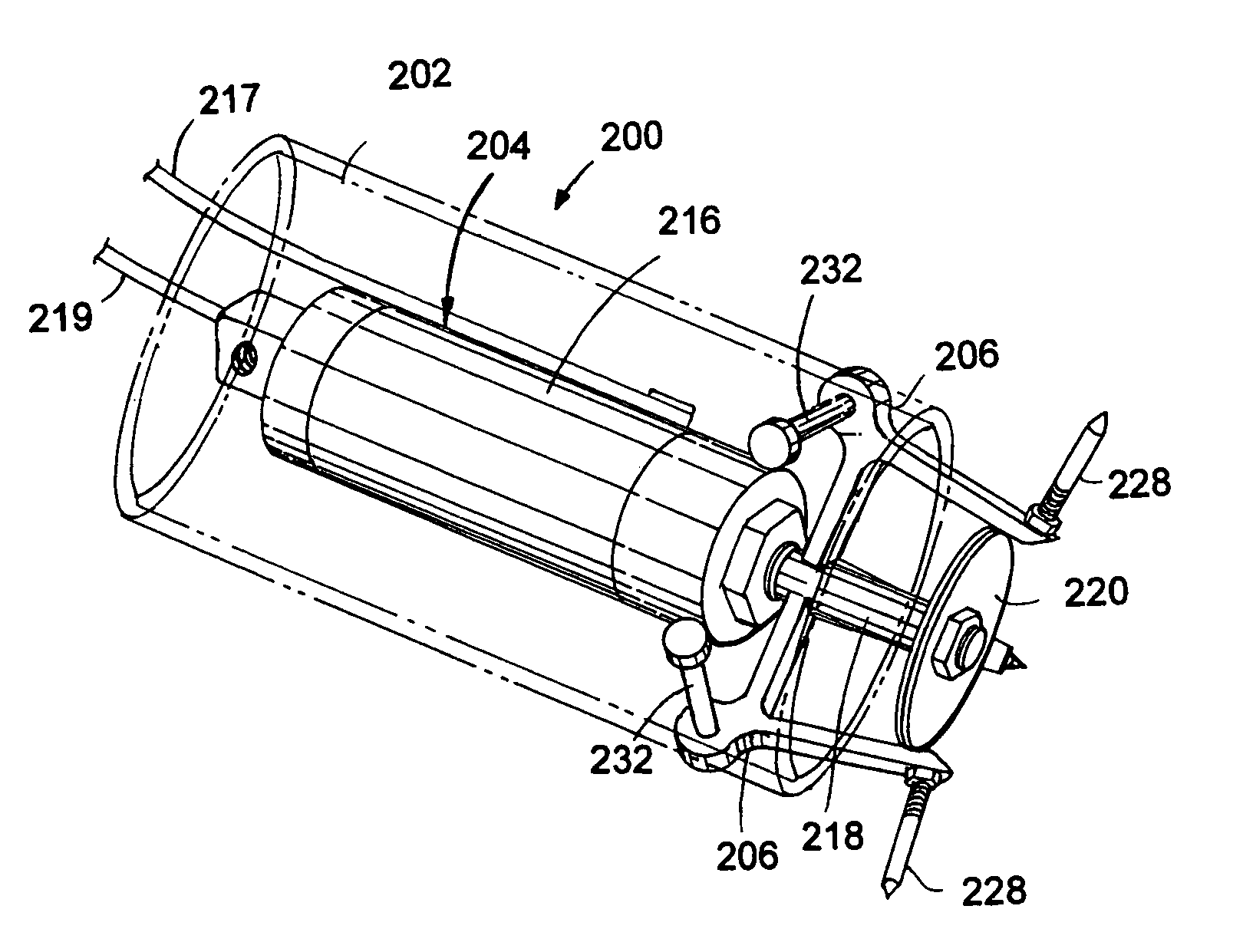
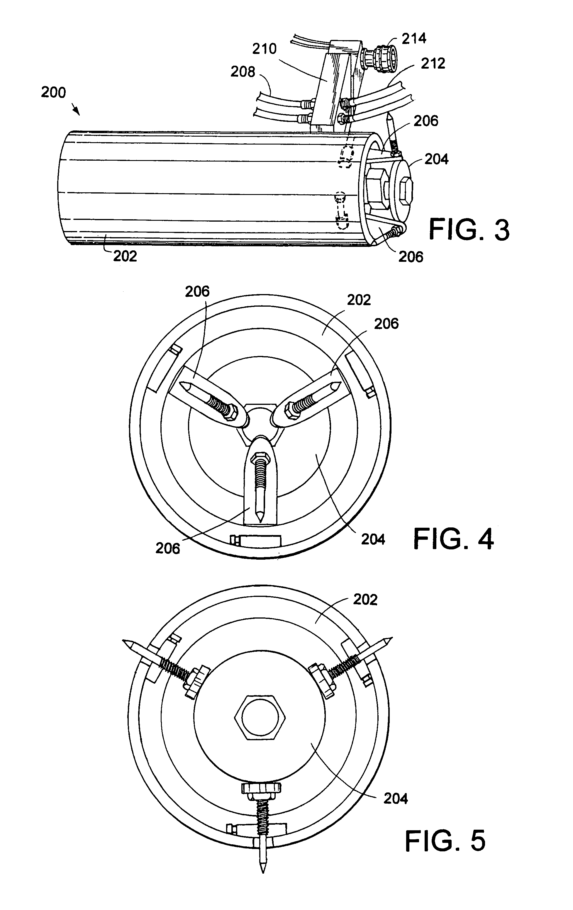
"The present invention provides a drain line re-perforator device for punching holes in clogged drain pipe sections in a sewage disposal system. The device is designed to be simple, inexpensive, and easy to operate by an unskilled workman. It includes an outer cylindrically-shaped housing member and a dual-actuating ram assembly disposed concentrically within the outer housing member. Three equally spaced-apart angled bracket members are mounted hingedly on the peripheral surface of the outer housing member and include a punch bit positioned for outward radial movement. The ram assembly is formed of a cylinder and a piston rod. The piston rod is moved in a reciprocal motion from a retracted position to an extended position so as to cause the angled bracket members to pivot outwardly and the punch bits to move outward radially for punching holes in the clogged drain pipe sections."

Problems solved by technology

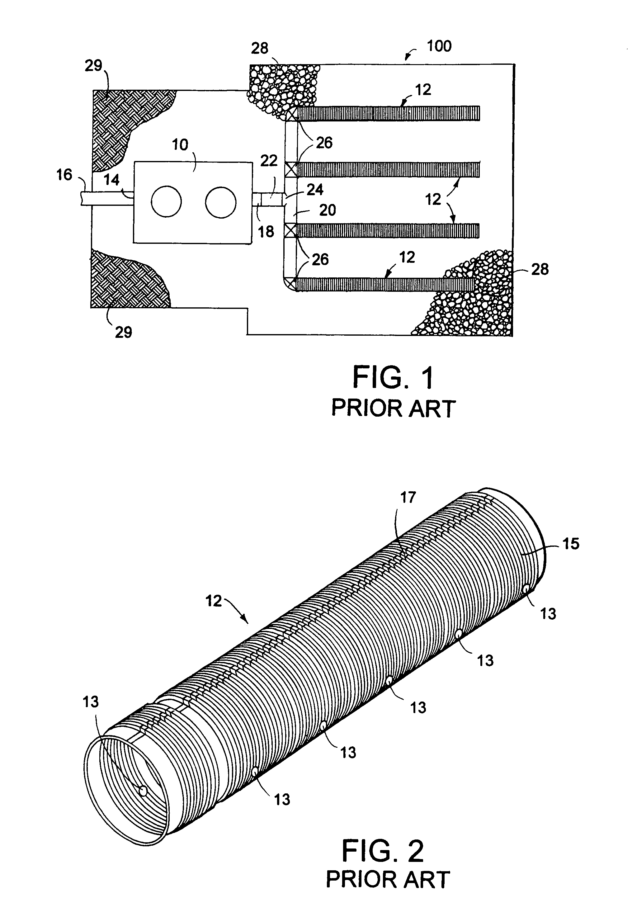
While the aggregate material 28 generally prevents the blockage of the pipe perforations, it has been encountered that after many years of using the sewage disposal system the perforations in one or more of the pipe sections 12 can become clogged or damaged and thus render the system inoperable.
This clogging or damage may be the result of many causes, such as soil movements, deterioration of the aggregate material, blockage of the holes in the pipe sections, and the like.
The conventional method of repairing the clogged or damaged pipe sections requires expensive and labor-intensive excavation, removal of the damaged pipe sections, and installation of new pipe sections.
The disadvantage of this prior art method is apparent when it is considered that the pipe sections are quite numerous extending up to a hundred feet or so and are buried commonly several feet underneath the backyard of the individual home.
Therefore, substantial expense can be involved in subterranean digging and repair under such conditions.
In addition, this prior art method can require a long period of time and during this time, use of the sewage disposal system is unavailable as well as the backyard of the home.

Method used


Image

  • Drain line re-perforator device
  • Drain line re-perforator device
  • Drain line re-perforator device

Examples


Embodiment Construction

[0038]It is to be distinctly understood at the outset that the present invention shown in the drawings and described in detail in conjunction with the preferred embodiments is not intended to serve as a limitation upon the scope or teachings thereof, but is to be considered merely as an exemplification of the principles of the present invention.

[0039]Referring now in detail to the drawings, there is illustrated in FIG. 1 a partial top plan view of a conventional sewage disposal system 100, such as would be buried under a backyard of an individual home located outside of areas serviced by community sewage treatment systems. As earlier described in the background of this specification, the sewage disposal system 100 includes the septic tank 10 and a drain field defined by a plurality of interconnected flexible corrugated drain pipe sections 12 extending from the distribution box or header pipe section 20. The header pipe section 20 is connected to the outlet port 18 of the septic tank...


PUM

PropertyMeasurementUnit
outer diameteraaaaaaaaaa
inner diameteraaaaaaaaaa
circumferenceaaaaaaaaaa

Abstract

A drain line re-perforator device for punching holes in clogged drain pipe sections in a sewage disposal system is provided. The re-perforator device includes an outer cylindrically-shaped housing member and a dual-actuating ram assembly disposed concentrically within the outer housing member. Three equally spaced-apart angled bracket members are mounted hingedly on the peripheral surface of the outer housing member and includes a punch bit positioned for outward radial movement. The ram assembly is formed of a cylinder and a piston rod. The piston rod is moved in a reciprocal motion from a retracted position to a an extended position so as to cause the angled bracket members to pivot outwardly and the punch bits to move outward radially for punching holes in the clogged drain pipe sections.

Description

BACKGROUND OF THE INVENTION[0001]1. Field of the Invention[0002]This invention relates generally to sewage disposal systems used in residential and commercial environments. More particularly, the present invention relates to a drain line re-perforator device for punching holes in clogged drain pipe sections in a sewage disposal system. Specifically, the drain line re-perforator device of the instant invention includes an outer cylindrically-shaped housing member, a dual-actuating ram assembly disposed concentrically within the outer housing member, and a plurality of angled bracket members mounted hingedly on the peripheral surface of the outer housing member so as to move outward radially punch bits for perforating drain pipe sections in a sewage disposal system.[0003]2. Description of the Prior Art[0004]As is generally known in the past, it has been typical to provide sewage disposal systems for individual homes, commercial buildings, and the like located outside of areas serviced...

Claims


Application Information

Patent Timeline
Patent Type & Authority Patents(United States)
IPC IPC(8): B26D3/00E21B37/00B26D5/12B26F1/00E03F1/00
CPCE03F1/002B26F1/0038Y10T83/0596Y10T83/392Y10T83/398Y10T83/8812Y10T83/8858
Inventor RUBINO, DANIEL L.
Owner RUBINO DANIEL L
Learn More