Method for harvesting and processing cells from tissue fragments

a technology of tissue fragments and cells, applied in the field of tissue removal and tissue grafting, can solve the problems of no suction while cutting, no removal of cut bone or tissue, one or more deficiencies, etc., and achieve the effect of less likely to damage normal tissue or joint surfaces

Inactive Publication Date: 2006-01-31
BONUTTI 2003 TRUST A THE +1
View PDF186 Cites 114 Cited by
  • Summary
  • Abstract
  • Description
  • Claims
  • Application Information

AI Technical Summary

Benefits of technology

[0013]The present invention is a percutaneous tissue removal apparatus including a flexible drill shaft and means for transmitting motion to the shaft. A cutting tip is mounted on the shaft to cut tissue fragments from the tissue. The tissue fragments are removed by suction along the flexible drill shaft to a location outside the body while cutting. One or more selected components of the removed tissue fragments may be collected for implantation, preferably into the body of the patient from whom they were removed. Because the drill shaft is ...

Problems solved by technology

Each of these, however, suffers from one or more deficiencies.
However, there is no suction while cutting, no removal of the cut bone or tissue, and no flexibility in the instrument.
U.S. Pat. No. 4,589,414 shows a surgical cutting instrument with a reci...

Method used


Image

  • Method for harvesting and processing cells from tissue fragments
  • Method for harvesting and processing cells from tissue fragments
  • Method for harvesting and processing cells from tissue fragments

Examples


Embodiment Construction

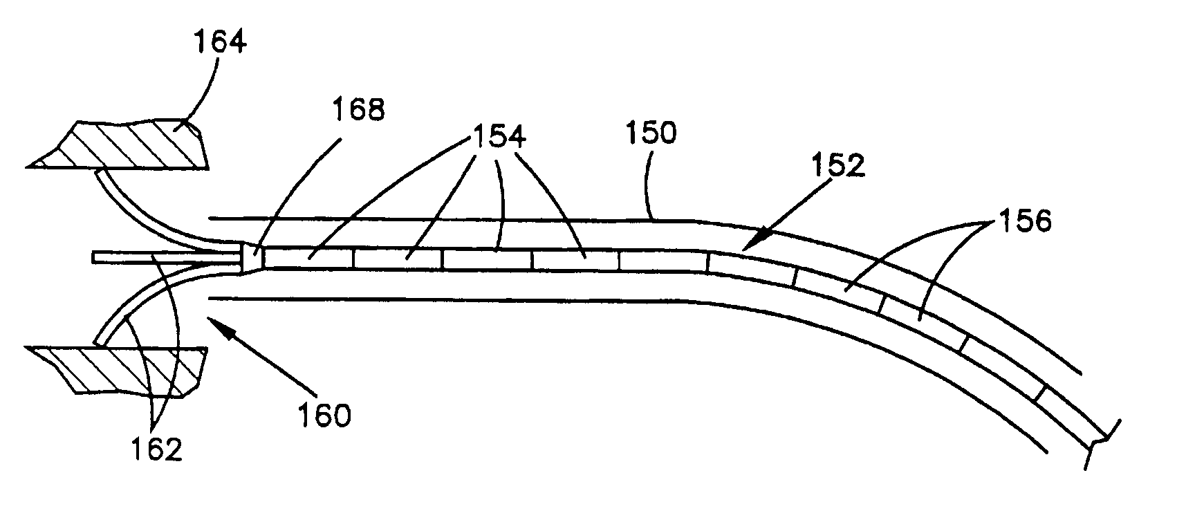
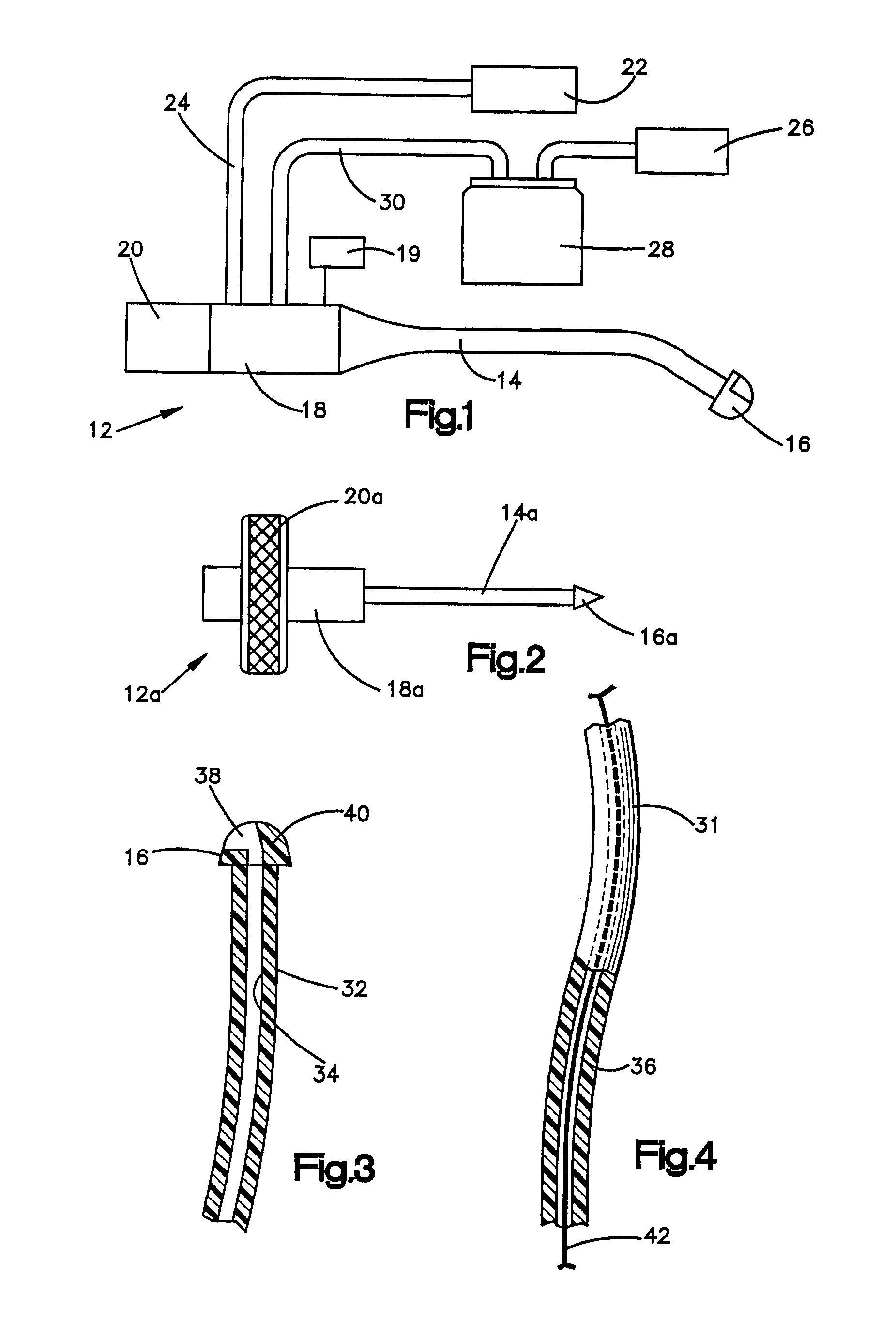
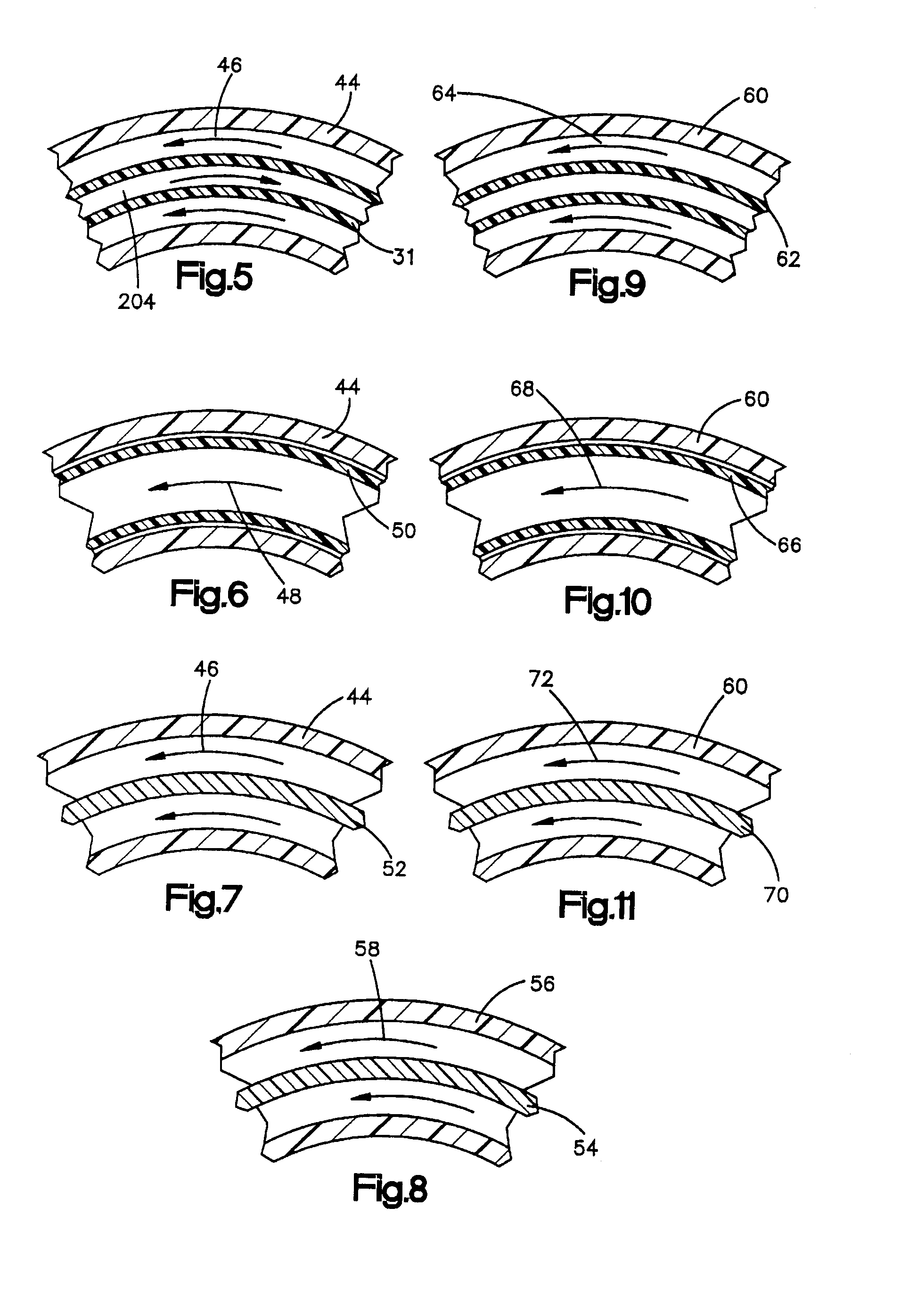
[0045]The present invention is described herein with reference to a percutaneous bone removal and harvesting apparatus and method. It should be understood that the present invention is not limited to the removal of bone tissue, but is useful in the removal of any hard or soft tissue in the body such as excess, unwanted, or tumorous tissue or tissue used for reimplantation or grafting.

[0046]A percutaneous bone removal apparatus 10 (FIG. 1) in accordance with the present invention includes a flexible drill 12. The flexible drill 12 has a flexible shaft 14 and a cutting tip 16 at the distal end of the shaft 14. The proximal end of the flexible shaft 14 is connected by a housing 18 to a motor or other power source 20 to provide rotational motion or reciprocating motion in a manner known in the art. Alternatively, the drill 12 may have an angled drive, such as 90.degree. drive or any angle, with the motor drive connected at an angle to the longitudinal extent of the suction and cutting a...


PUM


Abstract

A percutaneous tissue removal apparatus having a flexible drill shaft, a cutting tip mounted on the shaft a power source for transmitting motion to the shaft to move the cutting tip against tissue and a suction source for removing tissue fragments along the shaft to a location outside the tissue mass while cutting. The apparatus may include a container for collecting one or more selected components of the harvested tissue fragments for implantation of the fragments preferably into the body of the patient from whom they were removed. Where the tissue to be cut is bone, a cutting tip is preferably made of a polymeric material which is softer than the cortical portion of the bone, although the cutting tip may be made of a ceramic or a composite material. A second flexible shaft may be provided either within or about the flexible drill shaft.

Description

CROSS-REFERENCE TO RELATED APPLICATIONS[0001]This application is a continuation of U.S. patent application Ser. No. 10 / 044,388, filed Jan. 11, 2002, now U.S. Pat. No. 6,543,455 which in turn is a divisional of U.S. patent application Ser. No. 09 / 483,676, filed Jan. 14, 2000 now U.S. Pat. No. 6,468,289. The aforementioned application Ser. No. 09 / 483,676 is itself a continuation of U.S. patent application Ser. No. 09 / 323,326, filed Jun. 1, 1999 (now U.S. Pat. No. 6,174,313 B1). The aforementioned application Ser. No. 09 / 323,326 is itself a continuation of U.S. patent application Ser. No. 08 / 834,835, filed Apr. 11, 1997 (now U.S. Pat. No. 5,935,131). The aforementioned application Ser. No. 08 / 834,835 is itself a divisional of U.S. patent application Ser. No. 08 / 695,274, filed Aug. 9, 1996 (now U.S. Pat. No. 5,694,951). The aforementioned application Ser. No. 08 / 695,274 is itself a divisional of U.S. patent application Ser. No. 08 / 353,494, filed Dec. 9, 1994 (now U.S. Pat. No. 5,577,517...

Claims


Application Information

Patent Timeline
IPC IPC(8): A61B19/00
CPCA61B17/32002
Inventor BONUTTI, PETER M.
Owner BONUTTI 2003 TRUST A THE
Why Eureka
Try Eureka