Camera tripod rotating head

Inactive Publication Date: 2006-01-31
DAVIS ROBERT C
9 Cites 88 Cited by

AI-Extracted Technical Summary

Problems solved by technology

In most cases the inventions are very complex and fully automat...

Benefits of technology

[0017]Yet another object of the invention a simple bubble level is attached to the top of the head to assure that the photos align properly when the camera is rotated. This level is easy to use and adjustments in the tripod legs are easily made to assure the tripod mounting table is flat and level.
[0018]A final object of the invention is that the camera may be rotated in one direction only as the movement is controlled by a roller clutch. Cam type rollers are ...

Abstract

A camera tripod rotating head (20) is taught that is used for taking 360 degree photographic images with a camera (22) mounted on a tripod (24). The rotating head consists of an adapter base (26) that is configured to mate and attach to the camera tripod, and includes a one way roller clutch (30) mounted within the adapter base and a shoulder bolt (32) that is positioned through both the base and the clutch. A rotating beam (36) is attached to the adapter base with the shoulder bolt allowing the beam to revolve around the base a full 360 degrees in one direction only. Detents are position within the adapter base relative beam allowing the beam to be rotated and stopped at an equidistant predetermined location, preferably sixteen, until manually urged to the next location. An adjustable camera mounting bracket (60), configured to mate with the camera, is manually attached to the rotating beam permitting the rotating head, with a camera attached, to sweep in a one way arc of rotation stopping by the detents at each predetermined position.

Application Domain

Stands/trestlesKitchen equipment +3

Technology Topic

ClutchEngineering +3

Image

  • Camera tripod rotating head
  • Camera tripod rotating head
  • Camera tripod rotating head

Examples

  • Experimental program(1)

Example

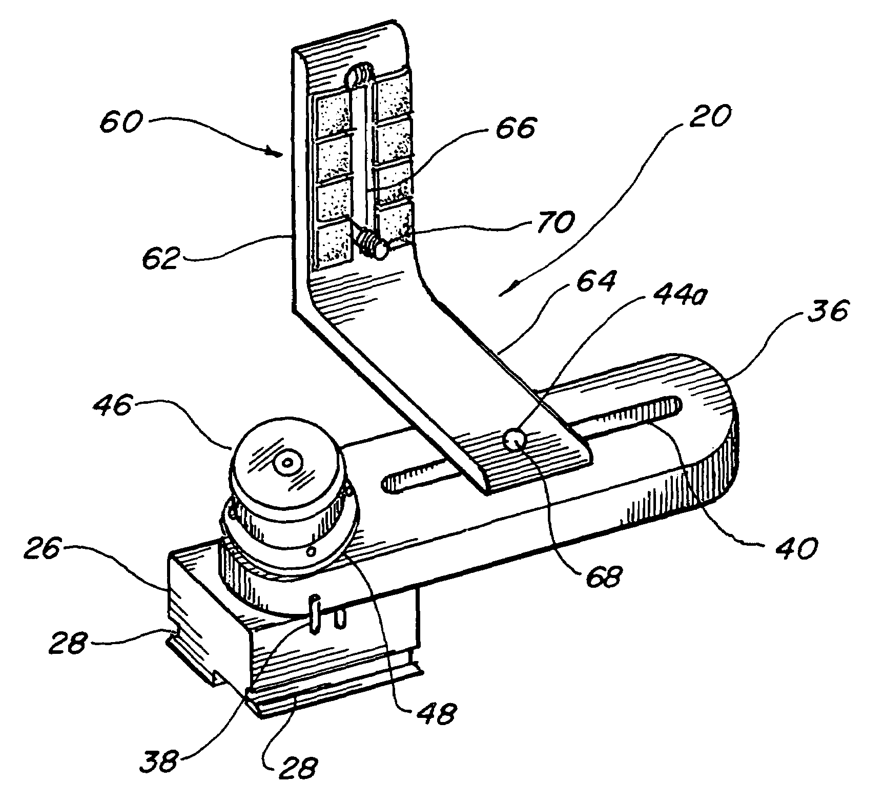
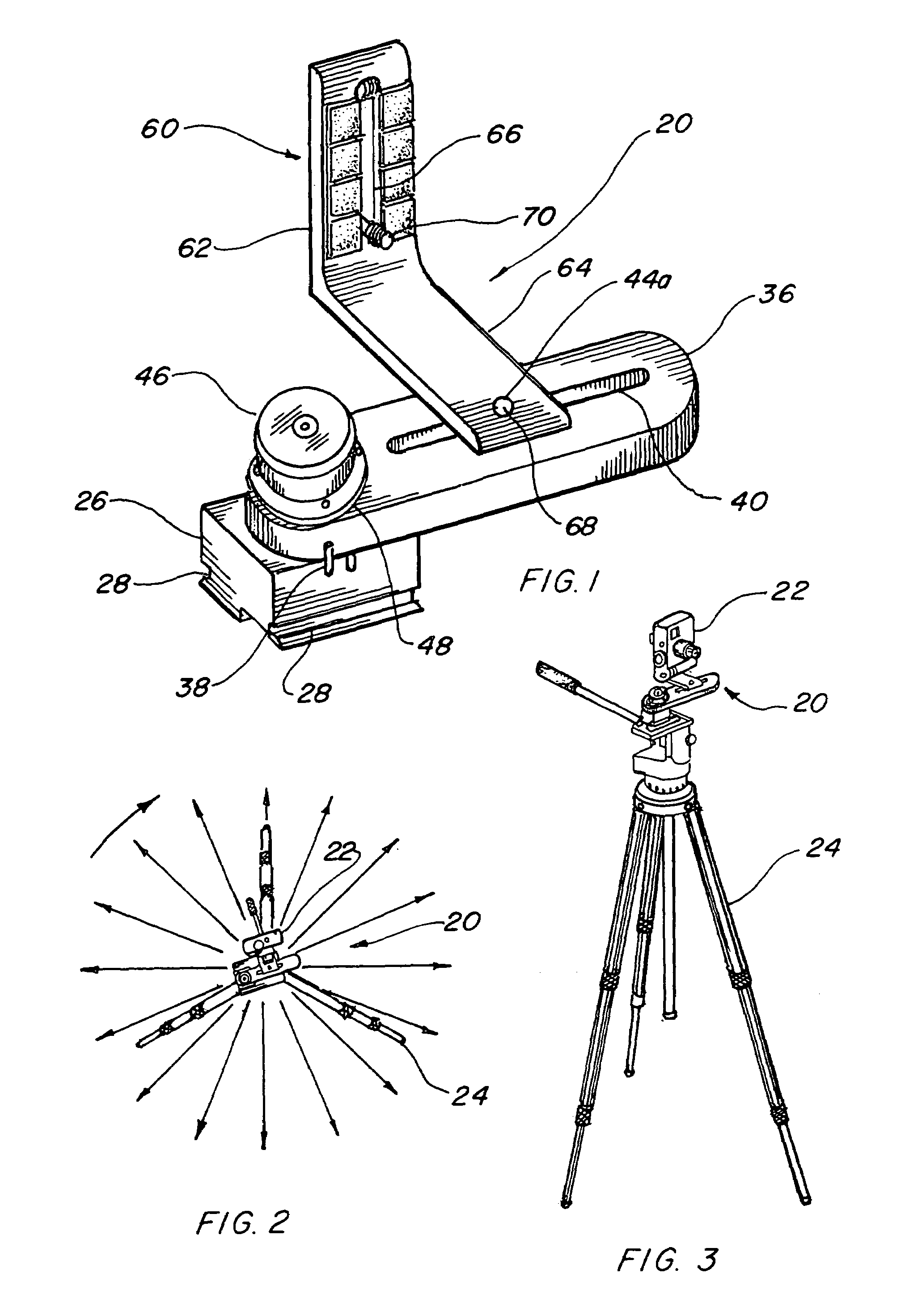
[0051]The best mode for carrying out the invention is presented in terms of a preferred embodiment. This preferred embodiment is shown in FIGS. 1 thorough 31 and is comprised of camera tripod rotating head 20 for taking 360 degree photographic images with a camera 22 mounted on a tripod 24. While the camera 22 and tripod 24 are not part of the invention the rotating head 20 permits the camera 22 to achieve the desired functional operation when mounted on the tripod 24.
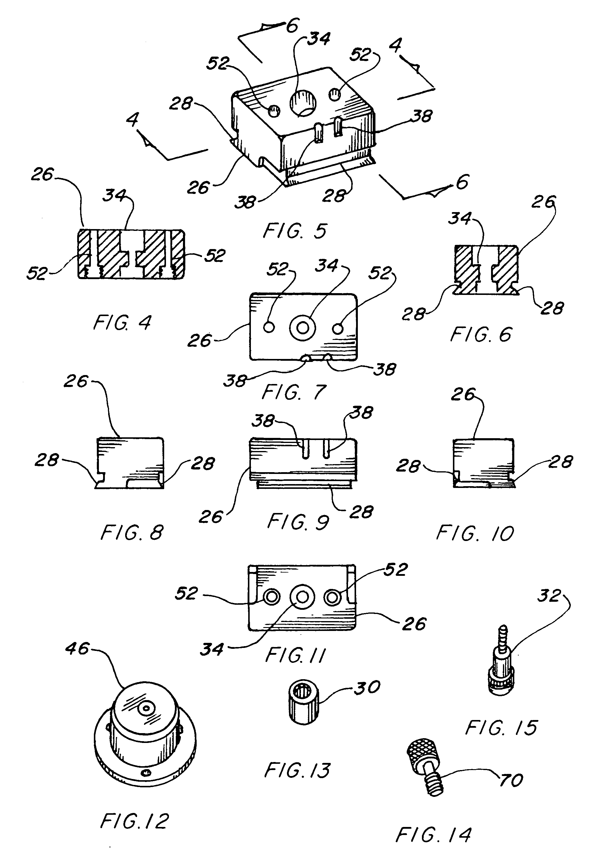
[0052]A tripod mounting adapter base 26, shown in FIGS. 5–11, is configured to mate and attach to a conventional camera tripod 24 having a dovetail groove. This attachment method is well known and a relative standard in the industry and therefore the rotating head 20 may be securely attached to the tripod 24 assuring a solid and repeatable junction therebetween.
[0053]The tripod mounting adapter includes a one way roller clutch 30 that is mounted within the approximate center of the adapter base 26 with a shoulder bolt 32 positioned through the clutch 30 with the head of the bolt 32 fitting into a counter bore 34 within the base 26, as shown in the cross section of FIGS. 4 and 6. The one way roller clutch 30, illustrated by itself in FIG. 13, in its preferred embodiment consists of a plurality of cam rollers that are circularly disposed within a housing sleeve such that when said shoulder bolt 32 engages the cam rollers the bolt 32 is permitted to rotate in one direction only and when it is reversed the cams rotate slightly and tightly grip the shoulder of the bolt 30 preventing rotation in an opposite direction.
[0054]A rotating beam 36, shown in FIGS. 17–23, is attached to the adapter base 26 with the shoulder bolt 32 allowing the beam 36 to revolve around the adapter base 26 a full 360 degrees, however, in one direction only. The adapter base 26 and the rotating beam 36 both include alignment grooves 38 therein providing an indexing indication for starting and stopping the rotation of the beam 36 when sequential photographic images are taken by the camera 22. The adapter base 26 preferably includes two alignment grooves 38 as shown in FIGS. 5, 7 and 9 while the rotating beam 36 preferably has a single groove 38, as illustrated in FIGS. 17 and 21.
[0055]The rotating beam 36 contains a bracket mounting slot 40 therethrough with a recessed shoulder 42 on the underside of the beam 36 as illustrated best in FIG. 18. A threaded hole 44 is located through the beam 36 that is positioned to interface with the shoulder bolt 32 which attaches the beam 36 to the adapter base 26 permitting the beam 36 to rotate freely in one direction only. The shoulder bolt 32 is sized to allow a gap to exist between the base 26 and the beam 36 therefore permitting rotation to be easily accomplished.
[0056]A surface mounted circular level 46 is attached to the rotating beam 36 at a position above the intersection with the adapter base 26, as shown in FIGS. 1 and 31, for positioning the tripod 24, on which the rotating head 20 is attached, to assure proper leveling of the head 20 for photographic purposes. The surface mounted circular level 46 is attached to the rotating beam 36 preferably with double sided pressure sensitive adhesive tape 48, however any other method of attachment may be used with equal ease and dispatch.
[0057]Detent means are provided for rotatably positioning the adapter base 26 relative to the rotating beam 36 in a predetermined location to accomplish the desired 360 degree sweep in an arc of rotation stopping at a series of predetermined positions allowing photographic images to be taken at each position. The detent means are defined as follows; the rotating beam 36 includes a plurality of radial cavities 50 that are situated in a circle radially disposed around the threaded hole 44 with the adapter base 26 including at least one hole 52, preferably two, therethrough with a steel ball 54, or the like, urged by a compression spring 56 held in place with a set screw 58 positioned within each hole 52. The balls 54 align with the radial cavities 50 such that when the rotating beam 36 is revolved around the shoulder bolt 32 the balls 54 penetrate the radial cavities (50) holding the beam 36 in place until manual pressure is exerted, retracting the spring loaded balls 54 and moving the beam 36 to the next aligned cavities (50). The gap between the beam 36 and adapter base 26 allowed by the shoulder bolt 32 is sufficient to permit rotation without binding.
[0058]The radial cavities 50 in the rotating beam 36 are positioned in the circle preferably 22.5 degrees apart making 16 discrete cavities 50 in the 360 degree rotation. It should be noted however, that any number of equal positions may be utilized to accomplish the same purpose and the invention is not limited to the specific number that have been described.
[0059]An adjustable camera mounting bracket 60 is manually attached to the rotating beam 36 to mate with a camera 22 and is adjustable to fit most conventional cameras and allow them to be located in the proper positional manner to accomplish the task at hand. The camera mounting bracket 60 has an angular shape formed with a vertical leg 62 and a horizontal leg 64. The vertical leg 62 has a camera mounting slot 66 and a threaded hole 44a is provided in the horizontal leg 64.
[0060]An attaching screw 68 connects through the bracket mounting slot 40 in the beam 36 into the bracket threaded hole 44a joining the bracket 60 to the beam 36 in an adjustable manner, as illustrated in FIGS. 1 and 31. A knurled thumb screw 70 is captivated within the camera mounting slot 66 for mounting a camera 22 onto the vertical leg 62. A resilient thermoplastic cushion 72 may optionally be connected to the mounting bracket 60 utilizing pressure sensitive backing which resiliently protects a camera 22 when it fastened to the bracket 60 with the knurled thumb screw 70.
[0061]The camera tripod rotating head's major components, which include the adapter base 26, rotating beam 36 and camera mounting bracket 60 are preferably made of a metallic material with aluminum being the most favorable. This aluminum or other material may be anodized, plated, painted or any other type of finish to prevent corrosion and add to its aesthetic appearance.
[0062]In function, a camera 22 is attached to the rotating head 20 which is positioned on a tripod 24 which is then manually adjusted with the circular level 46 on the head. The camera 22 is then rotated manually to sweep in an arc of rotation stopping by the detent means at the series of predetermined positions. A photographic image is taken at each position enabling individual images to be subsequently aligned together into a completed picture viewing surroundings as if a person were standing in one place and turning completely around.
[0063]While almost any camera may be used with the invention, including chemical film cameras, it has been found however that a digital camera having at least a definition of 2 megapixels is preferred. With this type of camera the image alignment is simple and the composition of the images may be easily transmitted and viewed on a computer and therefore transmitted on the internet. As previously stated the utility of the invention is best realized in the real estate industry where a listing may be digitally photographed and a brochure may be made of the complete structure then viewed and downloaded on the internet.
[0064]While the invention has been described in complete detail and pictorially shown in the accompanying drawings, it is not to be limited to such details, since many changes and modifications may be made to the invention without departing from the spirit and scope thereof. Hence, it is described to cover any and all modifications and forms which may come within the language and scope of the appended claims.

PUM

no PUM

Description & Claims & Application Information

We can also present the details of the Description, Claims and Application information to help users get a comprehensive understanding of the technical details of the patent, such as background art, summary of invention, brief description of drawings, description of embodiments, and other original content. On the other hand, users can also determine the specific scope of protection of the technology through the list of claims; as well as understand the changes in the life cycle of the technology with the presentation of the patent timeline. Login to view more.

Similar technology patents

Household appliance control method and device and mobile terminal

InactiveCN103605531Aeasy to operateeasy to use
Owner:GD MIDEA AIR-CONDITIONING EQUIP CO LTD +1

Multi-stage oral-fluid testing device

ActiveUS20160121322A1easy to use
Owner:PREMIER BIOTECH LLC

System and method of monitoring temperature

InactiveUS7140768B2less susceptible to tampereasy to use
Owner:COLD CHAIN TECH

Classification and recommendation of technical efficacy words

  • easy to use
Why Eureka
Try Eureka