Compactor wheel with trash exclusion properties

a technology of trash exclusion and compactor wheels, which is applied in the direction of construction, foundation engineering, roads, etc., can solve the problems of increasing the wear of the circumferential flange, the inability to meet the needs of replacement, and the inability to meet the needs of the entire compactor vehicle, so as to save fuel and vehicle operational wear, and the effect of efficient operation of the compactor vehicl

Active Publication Date: 2006-01-31
CARON COMPACTOR
View PDF9 Cites 57 Cited by
  • Summary
  • Abstract
  • Description
  • Claims
  • Application Information

AI Technical Summary

Benefits of technology

[0010]Still another object of the invention is to provide a compactor wheel that enables efficient operation of the compactor vehicle with concomitant savings of f

Problems solved by technology

Not uncommonly, the circumferential flange received higher wear that the nearby cleats and needed replacement long before the cleats needed replacement.
The tradeoff for attacking the trash entrainment problem on the wheel axles, as taught by the p

Method used


Image

  • Compactor wheel with trash exclusion properties
  • Compactor wheel with trash exclusion properties
  • Compactor wheel with trash exclusion properties

Examples


Embodiment Construction

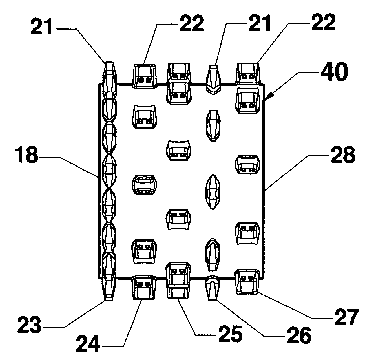
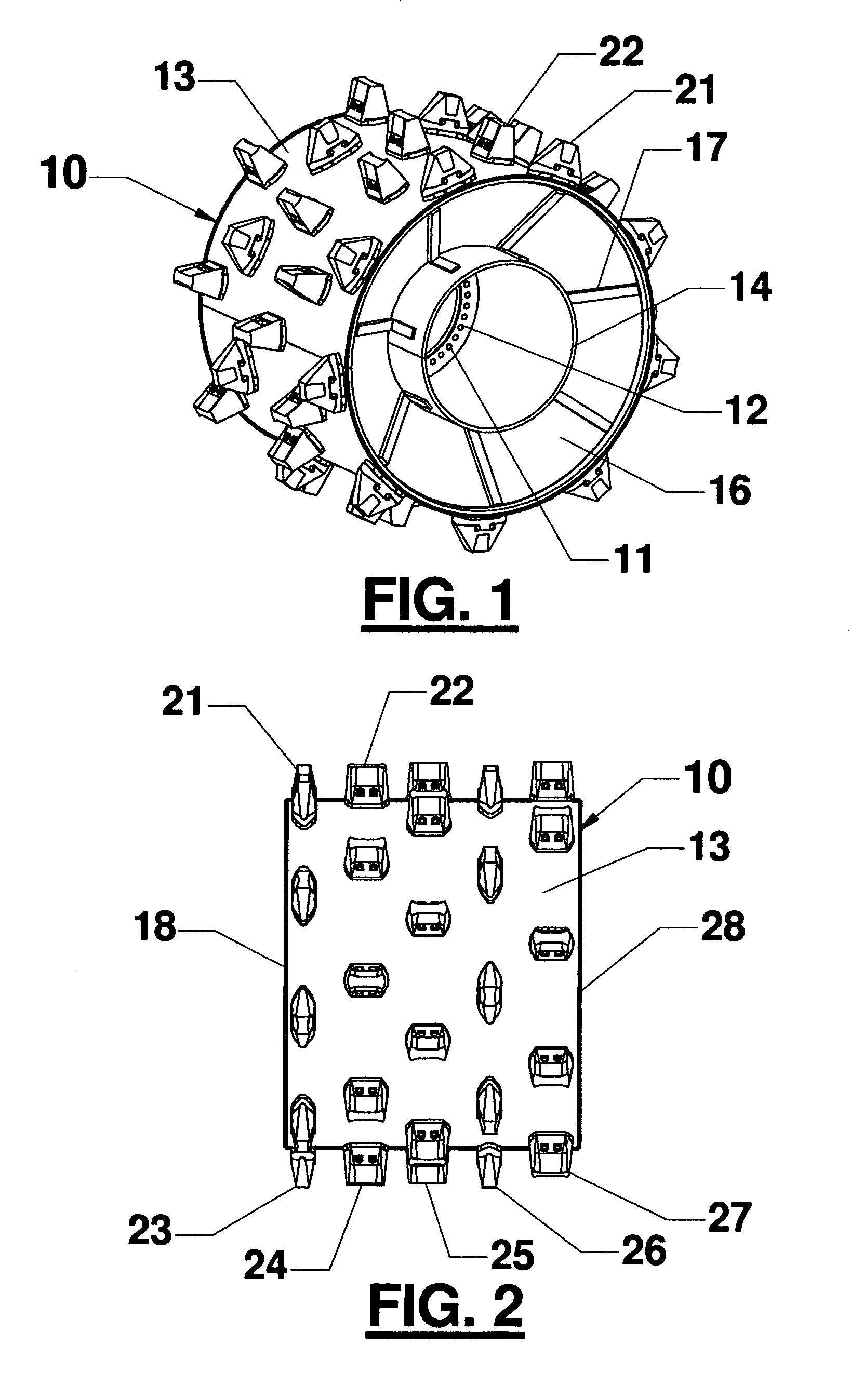
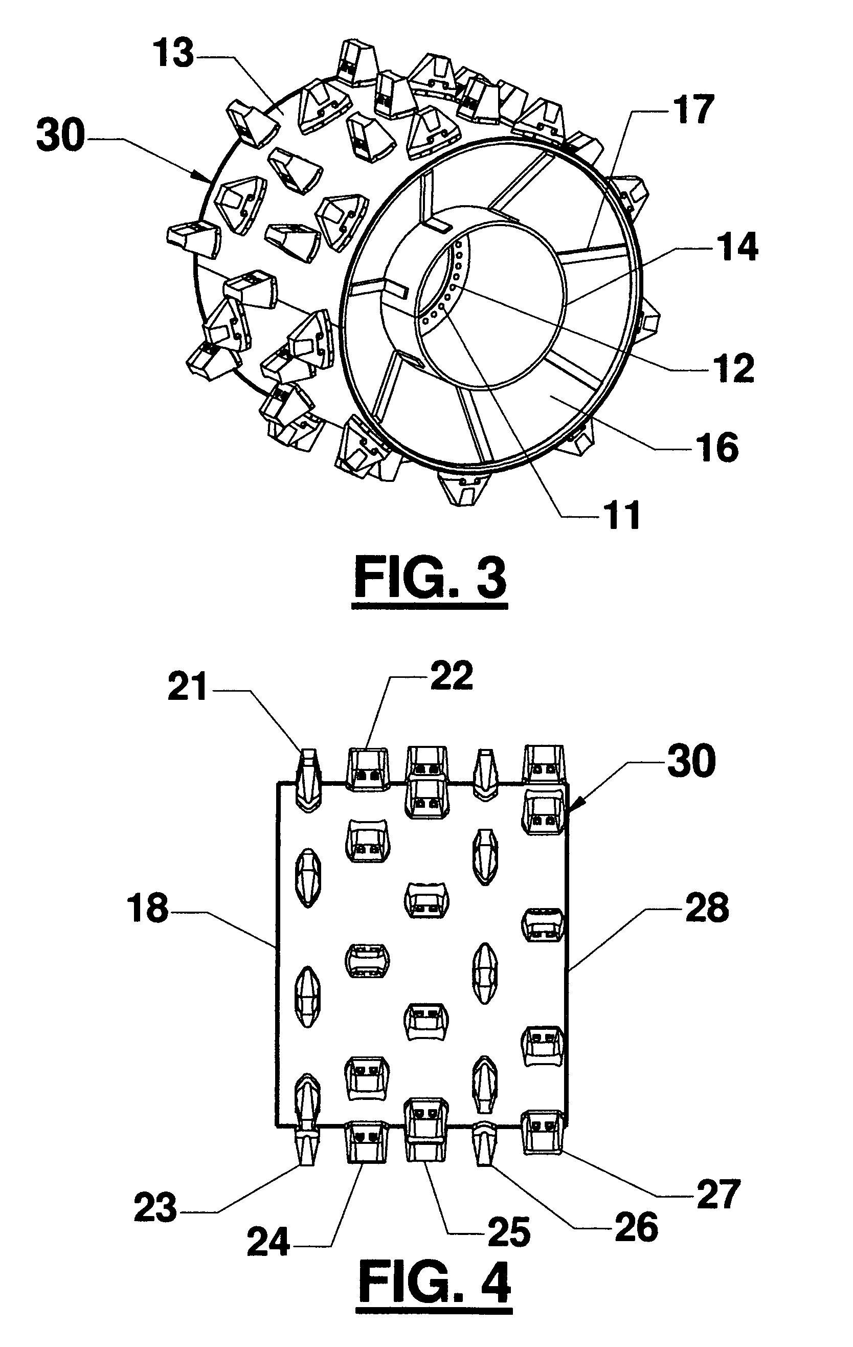
[0025]Referring to the drawings FIGS. 1 and 2, there is shown a first preferred embodiment, compactor wheel 10, that carries out the principles of the present invention. The wheel 10 is adapted to be operatively mounted on an axle of a compactor vehicle (not shown) it being understood that each of the four axles of the vehicle is equipped with one such wheel or the like. To effect mounting of the wheel 10 upon the vehicle axle a mounting ring 11 is provided with a plurality of holes 12 for receiving the wheel mounting studs of the associated vehicle axle (not shown) to be secured thereto with lug nuts (not shown) in the customary manner. The perspective view of FIG. 1 shows most prominently the inner face of the wheel, the face or side disposed closest to the compactor vehicle when the wheel 10 is mounted on the vehicle axle.

[0026]The wheel 10 further includes an outer drum 13, an inner drum 14 to which the mounting ring 11 is attached. A conically formed web member 16 rigidly secur...


PUM


Abstract

Landfill compactor vehicles having wheels equipped with wedge shaped cleats tend to accumulate about the vehicle's axle trash such as cable, wire, rope and the like debris requiring daily removal to permit unobstructed axle rotation. The wheel construction of this invention provides compaction cleats of two types, contour and traction, in rows positioned across the width of the wheel with substantially no cleat free zone adjacent the wheel edges but with a row of contour teeth arranged adjacent the wheel's inner edge thus affording trash exclusion properties to the compactor wheel.

Description

FIELD OF THE INVENTION[0001]This invention relates to the construction of land fill compactor wheels wherein wire, cable, refuse and debris entrainment around the landfill compactor's wheel axles can be a persistent operational and maintenance problem.BACKGROUND OF THE INVENTION AND PRIOR ART[0002]Landfill compactors are configured with wheels especially adapted to operate in sanitary land fills or refuse dumps. In that environment the first priority for such equipment is to obtain maximum compaction density of the materials deposited in the landfill thereby maximizing the capacity of the landfill. Typically a landfill compactor vehicle is self propelled and equipped with four large steel wheels. These wheels are each provided with an array of cleats that extend radially from a cylindrical wheel drum. By reason of the high compactor vehicle weight, sometimes amounting to 120,000 pounds (about 54,431 kg), the cleats mounted on the wheel drum apply localized forces to crush, grind and...

Claims


Application Information

Patent Timeline
IPC IPC(8): E01C19/26
CPCE02D3/026
Inventor CARON, JAMES OLIVER
Owner CARON COMPACTOR
Why Eureka
Try Eureka