Methods and modules for an underground assembly for storm water retention or detention

Inactive Publication Date: 2006-01-31
STORMTRAP
View PDF36 Cites 71 Cited by
  • Summary
  • Abstract
  • Description
  • Claims
  • Application Information

AI Technical Summary

Benefits of technology

[0024]FIG. 8 is a perspective view with a corner cut away of a third embodiment of an underground assembly

Problems solved by technology

The underground systems do not utilize valuable surface areas as compared to reservoirs, basins or ponds.
One disadvantage of current underground systems is that they must accommodate existing or planned underground facilities such as utilities and other buried conduits.
Another disadvantage of current underground sy

Method used


Image

  • Methods and modules for an underground assembly for storm water retention or detention
  • Methods and modules for an underground assembly for storm water retention or detention
  • Methods and modules for an underground assembly for storm water retention or detention

Examples


first embodiment

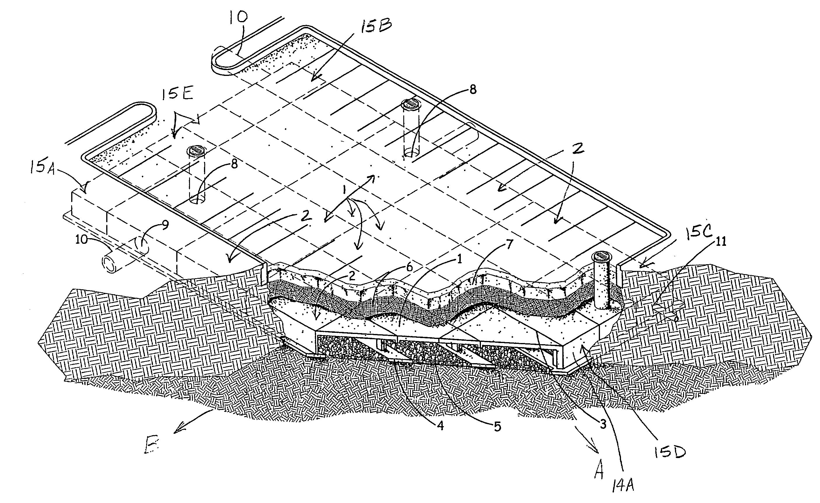
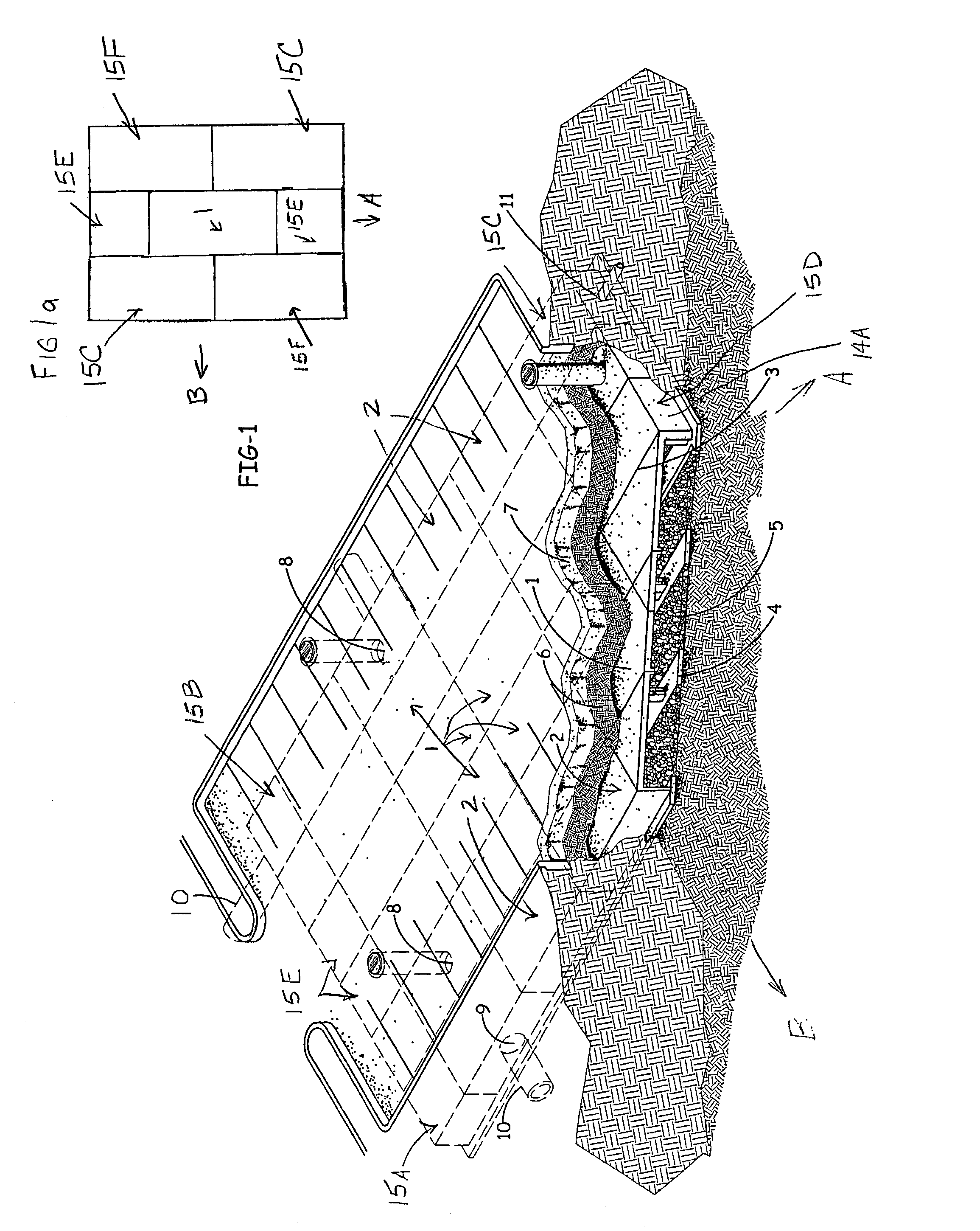
[0047]FIG. 1 illustrates an underground assembly for storm water retention and / or detention. The assembly of FIG. 1 is composed of a plurality of modules, such as interior modules, generally indicated at 1, and perimeter or side modules, generally indicated at 2. Each module will be described in more detail below. In FIG. 1 assemblies of modules are preferably placed in side-by-side and end-to-end configuration beneath a ground surface although the modules may also be spaced apart, as described below. Joints 3 between the modules are typically sealed with a sealant or tape such as, for example, bitmastic tape, wraps, filter fabric or the like. The length or width of the assembly of modules forming the channel is unlimited and may form irregular shapes such as the assembly illustrated in FIG. 9, which will also be described in detail.

[0048]In FIG. 1, the modules are preferably placed on footings or pads 4 which are positioned in a parallel and spaced orientation. The footings 4 may b...

second embodiment

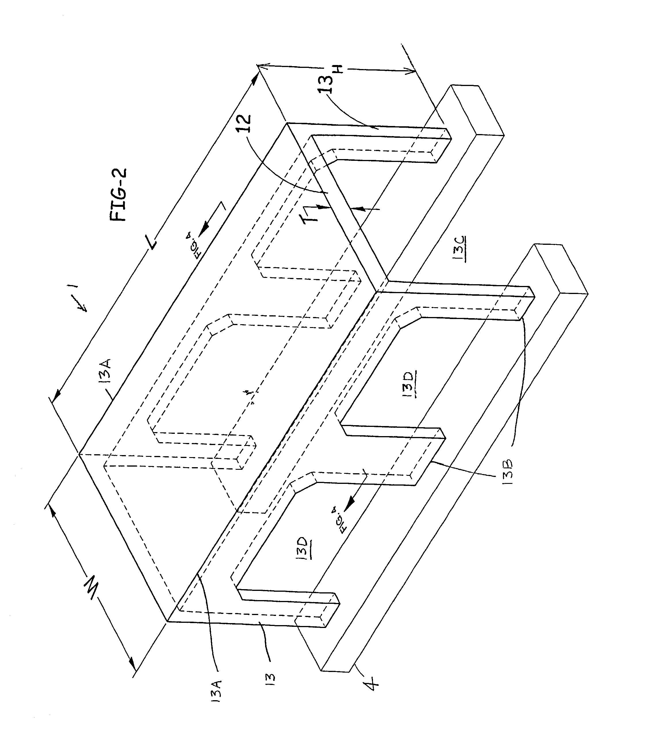
[0056]Turning now to FIG. 3, a module is illustrated in the form of a side module 2, which was previously identified in the assembly FIG. 1. The side module 2 is disposed peripherally of the interior module 1 in FIG. 1 and has some of the same parts such that the same numbers will be used to designate like parts. In FIG. 3 the side module 2 includes a corresponding substantially horizontally disposed deck portion 12 and two substantially vertically disposed side portions 13, 14 which extend from opposite longitudinal sides 13A of the side module deck portion. The side portions 13, 14 are preferably integrally connected to the deck portion. Together, the deck portion and side portions define a corresponding longitudinal channel 13E. The side portion 13 includes openings defined therein which defines lateral channels 13F, while another side portion 14 is without openings. The longitudinal and lateral channels 13E, 13F of the module 2 fluidly communicate with one another to allow relat...

fifth embodiment

[0059]In FIG. 1, a module is illustrated in the form of front end modules 15D which are placed between the front corner modules, only one front corner module 15C being shown. In FIG. 1, each end module 15D defines one longitudinal channel along its length and two lateral channels defined by its two side portions, similar to the previously described module 1, except that the front end module 15D further has a substantially vertically disposed end wall 14A which is preferably used to define an assembly outer boundary.


PUM


Abstract

Methods and modules for use in a modular assembly are disclosed for retaining or detaining storm water beneath a ground surface. A module comprises a substantially horizontally disposed deck portion and at least one substantially vertically disposed side portion extending therefrom. The deck portion and side portion have respective end edges, and the side portion has bottom edges. The side portion and the deck portion define a longitudinal channel which is open at least at an end of the module. The side portion has at least one opening therein and defines a lateral channel in the module. The longitudinal and lateral channels are in fluid communication with one another. Each channel has about the same cross section and extends upwardly from the bottom edges to allow relatively unconstrained flow in the longitudinal and lateral directions.

Description

BACKGROUND OF THE INVENTION[0001]The present invention generally relates to the retention or detention of fluids, typically storm water, but may have other applications. Storm water retention and detention systems accommodate runoff at a given site by diverting or storing storm water and preventing pooling of water at the ground surface.[0002]An underground storm water retention or detention system is generally utilized when the surface area on a building site is not available to accommodate other types of systems such as open reservoirs, basins or ponds. The underground systems do not utilize valuable surface areas as compared to reservoirs, basins or ponds. Underground systems are also advantageous in that they present fewer public hazards than other systems. Another advantage is that underground systems avoid having open, standing water which would be conducive to mosquito breeding. Underground systems also avoid the aesthetic problems of other systems such as algae growth and we...

Claims


Application Information

Patent Timeline
IPC IPC(8): E02B13/00E03F3/00E03F1/00E03F5/10
CPCE03F1/005E03F5/106E03F5/101
Inventor BURKHART, PHILIP J.
Owner STORMTRAP
Why Eureka
Try Eureka