
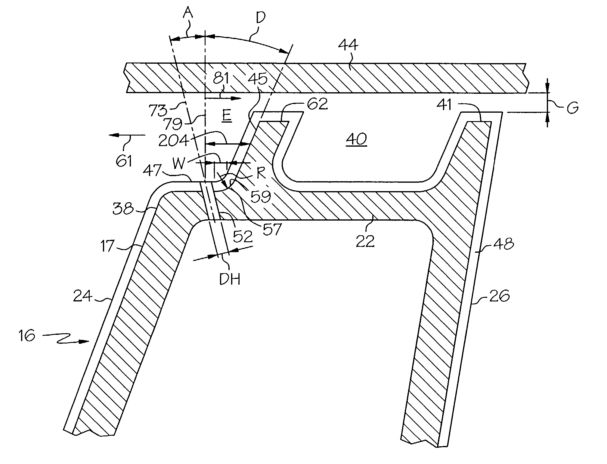
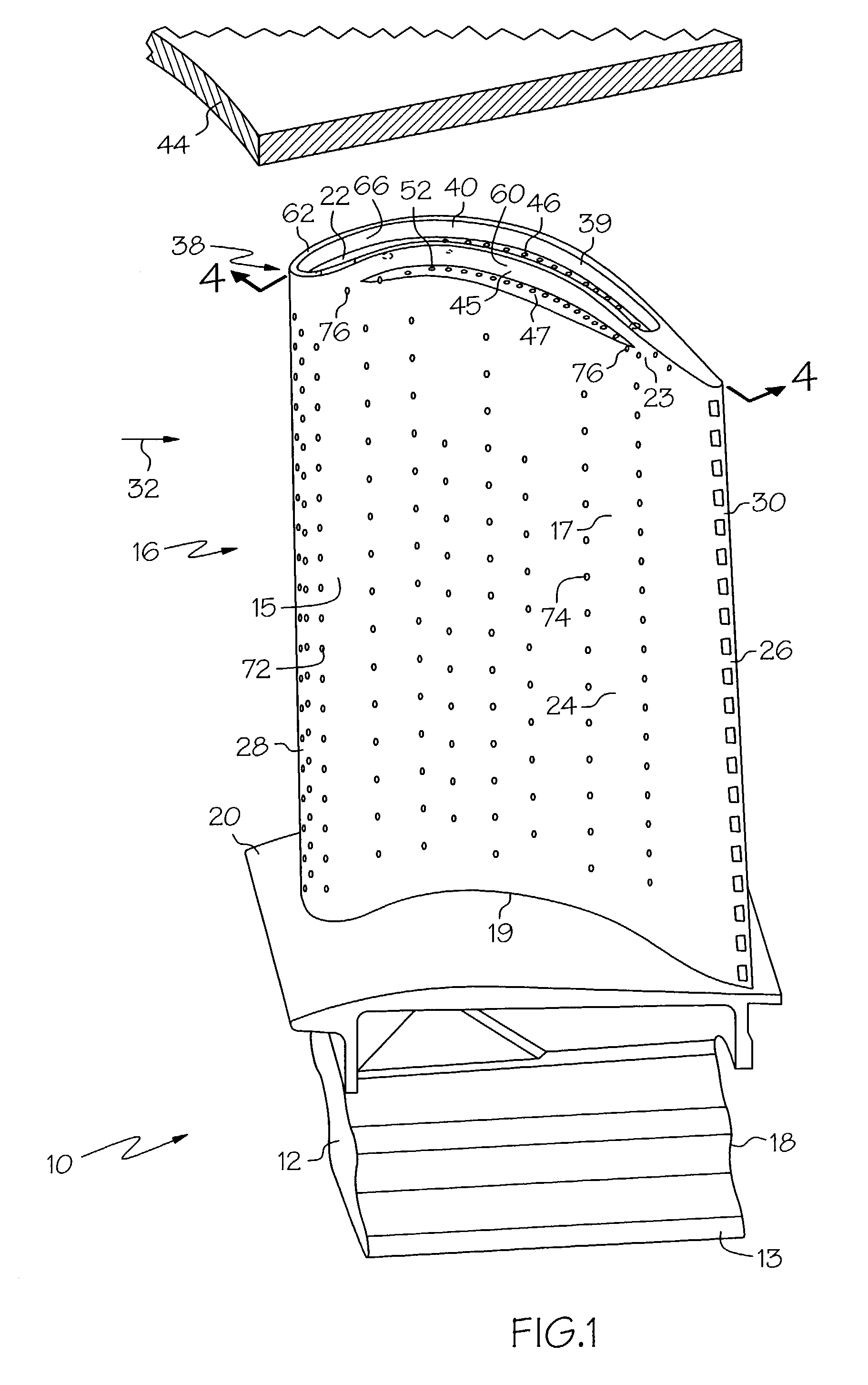
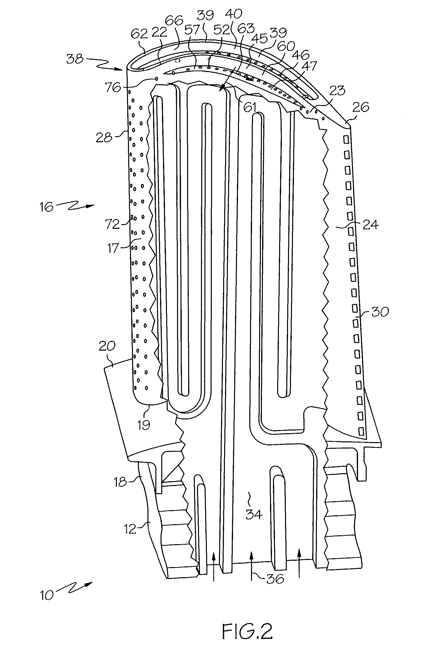
Turbine blade with recessed squealer tip and shelf

a technology of turbine blades and squealer tips, which is applied in the direction of machines/engines, liquid fuel engines, mechanical equipment, etc., can solve the problems of difficult boundary layer entrainment of cooling air flow along the exposed pressure side limited cooling effect of the squealer tip wall, and life-limiting elements

Inactive Publication Date: 2006-01-31
GENERAL ELECTRIC CO
View PDF10 Cites 85 Cited by
  • Summary
  • Abstract
  • Description
  • Claims
  • Application Information

AI Technical Summary

Benefits of technology

[0012]In a more particular embodiment of the turbine blade the first coordinate lines lie along transverse lines which are substantially shortest distances between the vertical lines are shortest distances between the vertical lines and the recessed tip wall portion. The shelf hole centerlines are spaced away from a fillet at the junction. The film cooling shelf holes extend into the fillet no more than 50 percent of a fillet wid

Problems solved by technology

The squealer tip typically operates at temperatures above that of the remainder of the airfoil and can be a life limiting element of the airfoil in a hot turbine environment.
It is difficult to entrain the cooling air flow in a boundary layer along the exposed pressure side of the squealer tip wall.
However, cooling of the squealer wall is limited in effectiveness, and thermal gradients and stress therefrom are created which also affect blade life.

Method used


Image

  • Turbine blade with recessed squealer tip and shelf
  • Turbine blade with recessed squealer tip and shelf
  • Turbine blade with recessed squealer tip and shelf

Examples


Embodiment Construction

[0022]Illustrated in FIGS. 1 and 2 is an exemplary gas turbine engine turbine rotor blade 10 configured for use as a first stage high pressure turbine blade. The blade 10 includes a dovetail 12 having suitable tangs 13 for mounting the blade in corresponding dovetail slots in the perimeter of a rotor disk (not shown). The blade 10 further includes an airfoil 16 joined to the dovetail 12 at an airfoil base 19 at an integral platform 20 and a squealer tip 38 at a radially outer end 23 of the airfoil. The squealer tip 38 includes an airfoil shaped squealer tip cap 22. The airfoil 16 further includes a continuous outer wall 15 with laterally opposite pressure and suction sides 24 and 26, respectively, extending longitudinally between a leading edge 28 and an opposite trailing edge 30 and radially from the airfoil base 19 to the tip cap 22. The airfoil is designed to withstand the deteriorating effects of a hot flowpath gas 32.

[0023]The airfoil 16 further includes an internal cooling cha...


PUM


Abstract

A turbine blade squealer tip has a continuous squealer tip wall extending radially outwardly from and continuously around a tip cap. A recessed tip wall portion of the tip wall is recessed inboard from a pressure side of an airfoil outer wall of an airfoil of the blade forming a tip shelf therebetween. A plurality of film cooling shelf holes are disposed through the tip shelf to an internal cooling circuit of the blade and are spaced away from a junction between the recessed tip wall portion and the tip shelf. The exemplary embodiment of the airfoil includes shelf hole centerlines of the holes passing through pierce points in the shelf. At least a majority of the shelf hole centerlines are angled in outboard directions away from and outboard of the squealer tip wall. A majority of centerlines are angled away from vertical lines passing through the pierce points at first component angles in a range between 2 degrees and 16 degrees.

Description

GOVERNMENT INTERESTS[0001]The U.S. Government may have certain rights in this invention in accordance with Contract No. N00019-96-C-0080 awarded by the Dept. of the Navy.BACKGROUND OF THE INVENTION[0002]1. Field of the Invention[0003]The invention relates generally to gas turbine engine turbine blade squealer tip cooling and, more specifically, to turbine blade squealer tips cooled using cooling holes through a tip shelf.[0004]2. Description of Related Art[0005]Gas turbine engine turbine blades extract energy from hot combustion gas for powering the compressor and providing output power. Since the turbine blades are directly exposed to the hot combustion gas, they are typically provided with internal cooling circuits which channel a coolant, such as compressor bleed air, through the airfoil of the blade and through various film cooling holes around the surface thereof. One type of airfoil extends from a root at a blade platform, which defines the radially inner flowpath for the comb...

Claims


Application Information

Patent Timeline
IPC IPC(8): F01D5/18F01D5/14F01D5/20
CPCF01D5/141F01D5/20F05D2260/202
Inventor STEC, PHILIP FRANCISDEMERS, DANIEL EDWARDSCHMIDT, RICHARD LUDWIG
Owner GENERAL ELECTRIC CO
Learn More